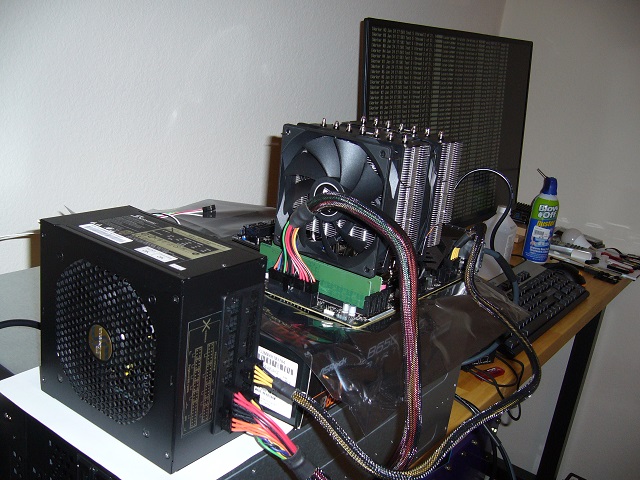
 Bench assembly/testing. You can see Prime95 (mprime) running. The Asrock BIOS has a nice set of PBO presets - I tested this one at 85C/-40mV, and set
it to run at 75C/-30mV. Max clock is ~5.3GHz; it can sustain ~4.9GHz on all cores at maximum load (AVX512), at 75C, of course.
This is actually the second motherboard. I cracked a couple corners off of the B650 die on the first while fitting a Zalman NB-47 - the die is tiny, and I rocked the heat sink just a bit. Ooops. I decided that the chipset can just stew, as it's in the air path from the system fan. A better heat sink would be nice, but hey.
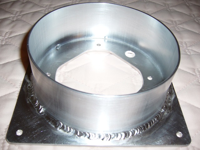
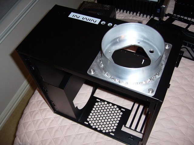
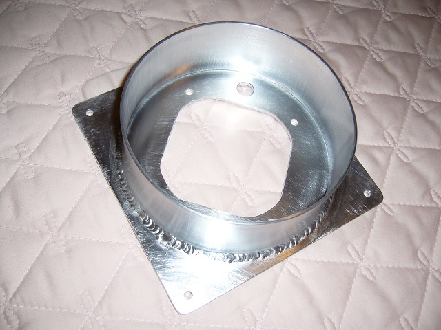 Here is the fan and filter mount. It is a square piece of 1/8" 6061 sheet with a 5" OD, 1/16" wall 6061 tube stub welded to it. Both pieces were
leftovers from Ares6.
The 1/8" base resists distortion from welding... somewhat. Screwing it all together takes care of the warpage. I had this welded at the same shop that welded the flange on Ares6 - I slid in right before they closed the business. Another small custom shop gone.
The 5" tube is large enough to allow me to mount an 80mm fan inside the tube (and thus inside the filter), while being small enough fit the 301. More on that below.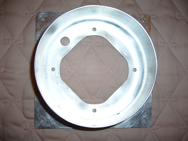
 I needed to poke some holes in the faceplate of the 301, which is most easily done with said faceplate in a horizontal position. Unfortunately the
301 does not have a flat backside, so I cut some reliefs in a piece of scrap plywood to use as a base.
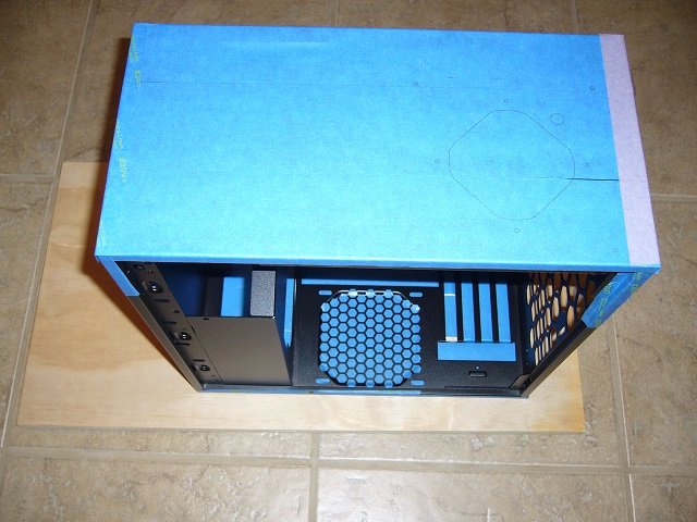 Here's the 301, all taped up and marked. I tried to cover every surface that I might ding up, top and bottom (technically front and back).
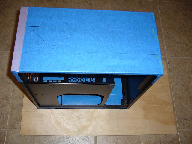
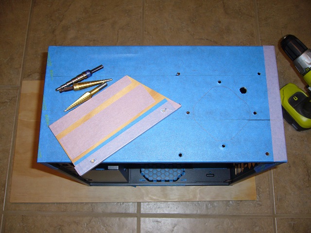
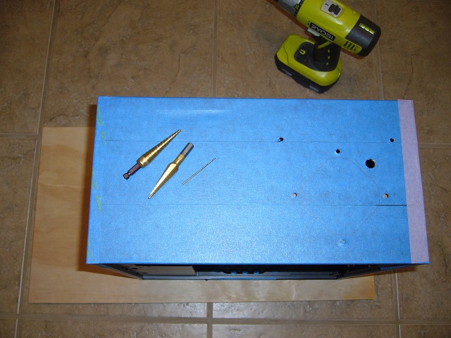 Here it is with some of the cutting tools and a few holes drilled. I pilot the holes with a small twist drill, as it's tough to center punch the
(relatively) thin sheet metal without distorting it. For the bulk of the holes I use a step bit, as it has no twist, so it's easy to control and
makes a nice smooth hole.
You can see something peeking out of some of the holes...
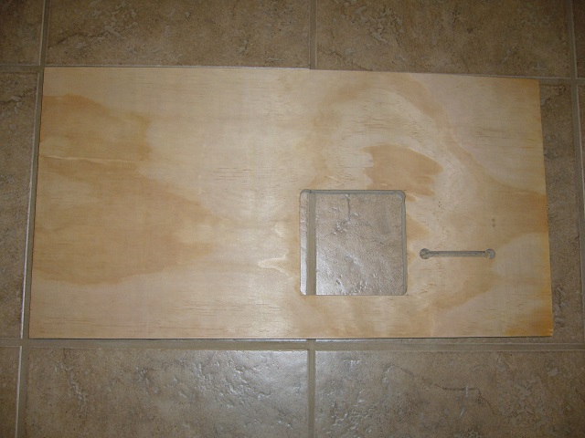
 ...And here's the piece - a bit of 1/4" ply that I used to back up the holes near the edge, so I wouldn't drill into the stamped-over edge below.
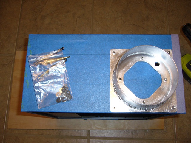 It seems to fit.
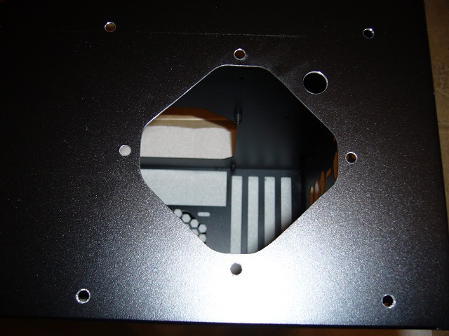
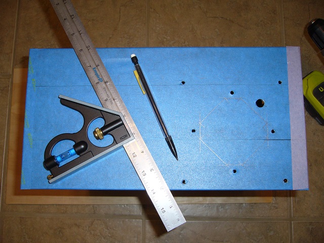 Now all I have to do is munch a bigger hole in the middle. I marked it up using the actual flange as a guide.
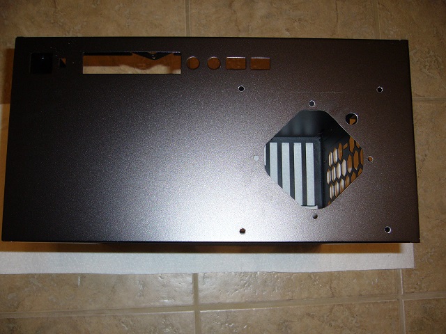 And the hole is made. I used a Dremel (-type tool) with abrasive wheels and some sanding drums.
This view also illustrates the rather tight fit. Even though the faceplate is ~7.25" wide, the switch/LED/USB panel eats much of it. I actually fabricated the flange without mocking it up for fit, and I got lucky.
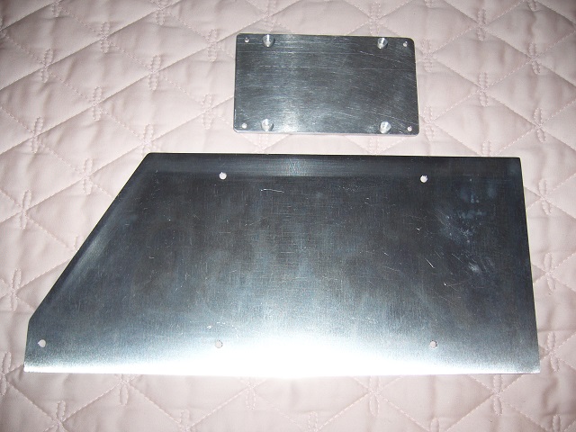 The bottom of the 301 is heavily ventilated, which is detrimental in this application. So I made up a blockoff sheet out of a piece of .050"
aluminum scrap. I cut the corner to provide a bit of airflow to the bottom expansion card.
The other piece is one of the failed SSD mounts from the HDPlex H3v3...
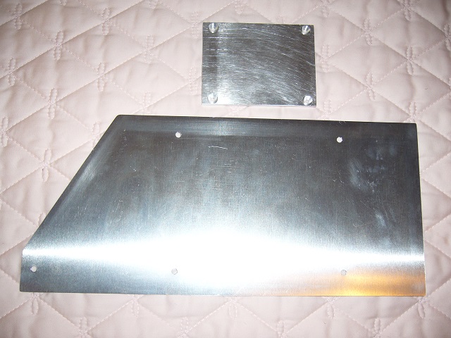 ...Which, with the ends lopped off, will make a fine spacer (a flush mount is not practical since U.2/U.3 cables protrude below the bottom surface of
the SSD). The countersinking on the holes is irrelevant to this application, since the screws will run straight through both aluminum pieces.
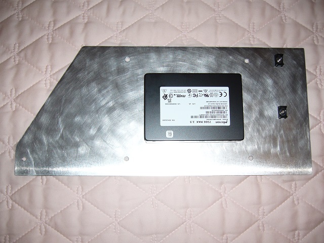 Here is the blockoff sheet all scrubbed up with the SSD and a couple cable tie mounts mounted.
The SSD is a baseplate-cooled device (controller on the bottom of the circuit board with a thermal pad coupling it to the baseplate), so I applied a few square inches of thermal compound between the SSD and spacer and the spacer and blockoff sheet. Combined with direct airflow from the system fan, this arrangement cools the SSD quite effectively.
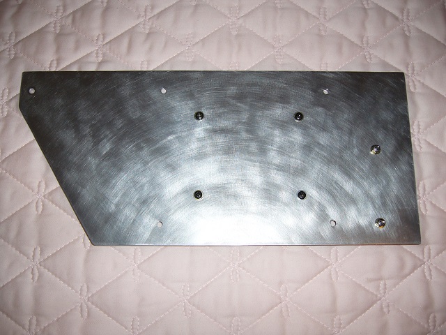 Bottom view. Everything is placed very deliberately, as you'll see once it's mounted.
Note that the cable tie mount for the SSD is centered on the connector, not on the SSD body.
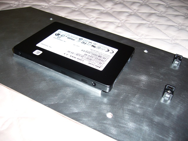 A view of the spacer.
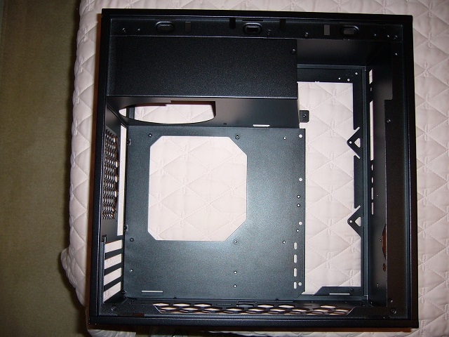 A view of the inside of the empty case.
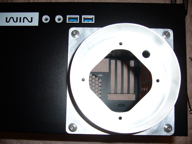 Flange installed.
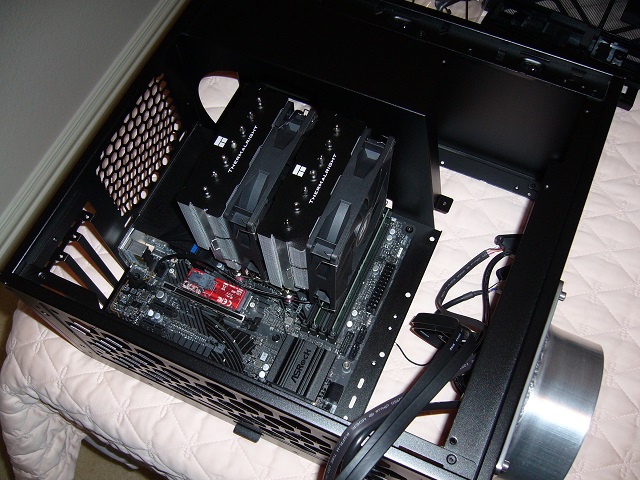 And the motherboard installed. Pretty tight fit.
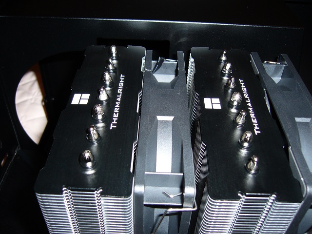 The heat sink is a Thermalright Phantom Spirit 120 SE. It fits. I did verify that as well as possible prior to purchasing it.
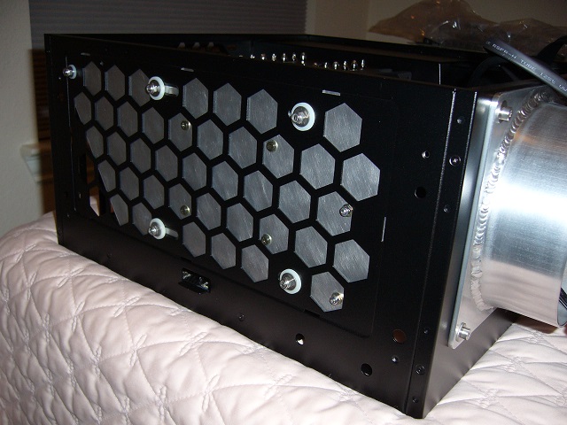 Blockoff sheet installed. You can see the reason for the component placement - the SSD only fits centered (more toward the side panel would be
preferable; farther back would crowd the bottom PCI-e slot) and the cable tie mounts are as far away from it as practicable (too far forward would
be problematic as well).
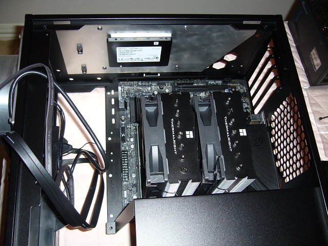 Inside view of the blockoff sheet and SSD.
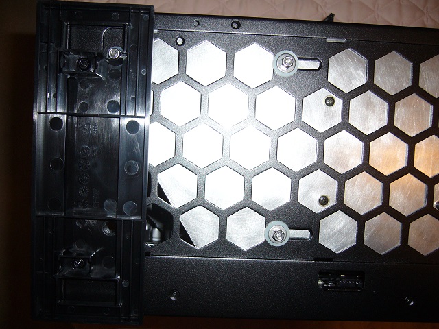 The rear foot is a close fit to that mounting bolt.
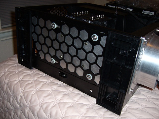
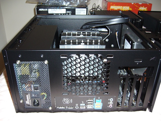 Just a view from the back of the case.
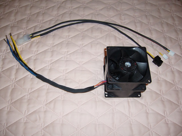 The fan is a San Ace 9CR0812P8S03 80mm 12V dual counter rotating fan, 66W and 160CFM at maximum output, with PWM speed control and dual tach outputs.
This model is discontinued; I chose it because it is slightly less powerful (and therefore quieter) than the current model.
The junction between the fan wiring and pigtail is a 6-position Mini-Fit Jr. The fan has eight wires: +, -, tach, PWM for each motor. I combined the +, -, and PWM and separated the tach outputs, so 5 positions. The housing is not installed on the fan side as it will not fit through the hole in the faceplate.
On the pigtail, the tach and PWM are wired to standard KK connectors, allowing motherboard control and monitoring. Power is an 8-position PCI-e-style Mini-Fit Jr to plug into the Seasonic Prime Titanium 650W power supply, as 5.5A is way too much for the motherboard connectors... and approaching the limit of a single Mini-Fit Jr contact. The fan should never run at full speed in any case - but it can.
I get a little bit crazy with heat shrink tube colors. Yellow is traditionally 12V, but any positive voltage may be red as well, e.g. with fan cabling, where red is 12V and yellow is tach. So the color coding here is a bit wacky. Normally I use orange for 3.3V, red for 5V, yellow for 12V, blue for 18-24V, black for -, green for ground, and... er, white or blue for signals (like the blue PWM here). Sigh. I need more colors. Or fewer.
Something you can't see here (but you can on Ares5) is that I use all white wire. I buy expensive irradiated PVC (or equivalent) insulated wire that won't melt when soldered, so buying all white wire and a pack of Sharpies is the cheap way to go. Just remember to mark 'em. or you'll be chasing 'em with a multimeter later.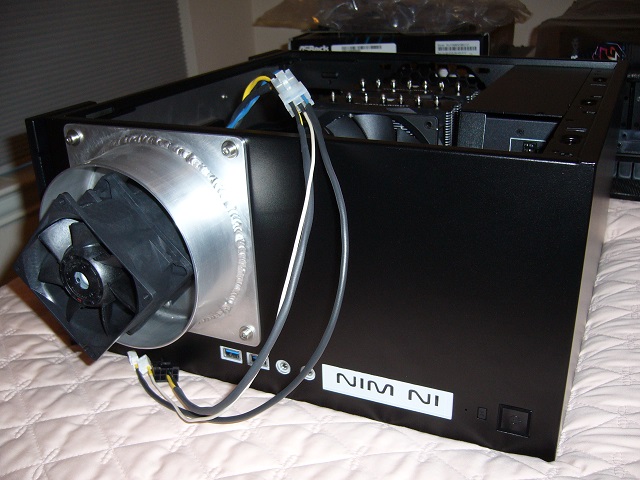 And here it is installed.
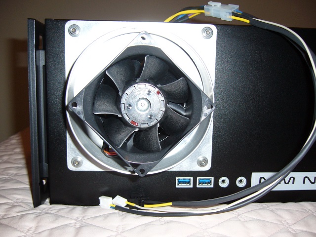
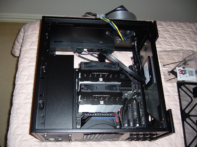 A bit tough to see here, but I used plain nuts on the flange and nylocks on the fan. The flange is all metal to metal, so the plain nuts are quite
secure, but the fan housing is nylon, so I couldn't crank those down quite so much. Locking nuts will stay in place.
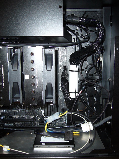 Argh! Cabling nightmares!
The cables are a bit of a mess. Other folks could probably do a neater job, but they are fairly secure.
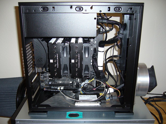 Finished, all tied down.
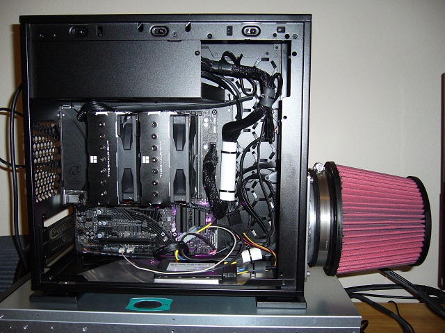 Here the filter is installed and the machine running (thus the pretty lights around the chipset). The filter is an AEM 21-2073DK. It presents a
typical pressure drop for this type of filter, ~.25" H2O. The fan is easily capable of handling this.
This view also shows the ATX12V cable. I don't really like the single-insulated ribbon-type cables Seasonic included with the Titanium supplies, so I shrank a tube over a section of it. You can't really tell in the photo, but the cable is effectively isolated by the shrink tube as installed.
You can see the front panel audio cable at the bottom - juuust long enough.
You can also just barely see the NVME signal cable where it's tied down and runs over the chipset heat sink. It is very close, but does not make contact.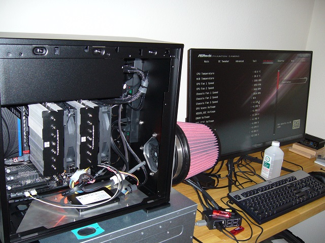 You can see the tach outputs on the display - they work.
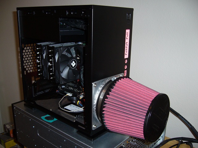 The front panel LEDs almost match the filter.
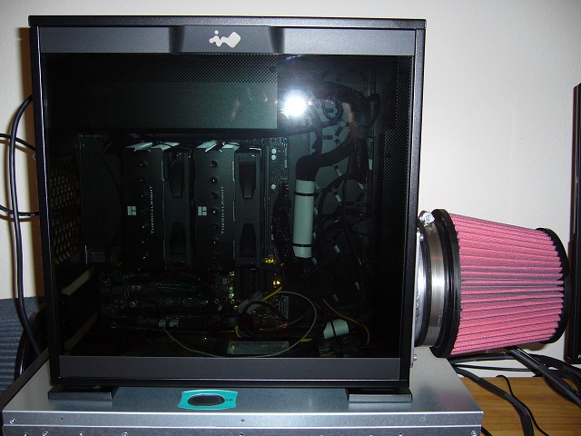 Complete. It's a bit louder than I'd hoped, as the fan seems to ring the case a bit.
As with Ares6 I use the "Motherboard" temperature source to control the system fan. It seems to track ambient temperature fairly accurately, so is more appropriate than the "CPU" source. As the ambient temperatures of interest fall into a narrow band, I have the speed control set for 5, 7, 10 and 20% at 28, 30, 32 and 34C respectively. Naturally I determined the setpoints using the scientific rule of thumb.
Also as with Ares6, the airflow is surprisingly linear. It wants to head straight through. Much different than the right-angle flows that I'd used previously, where the air would distribute radially.