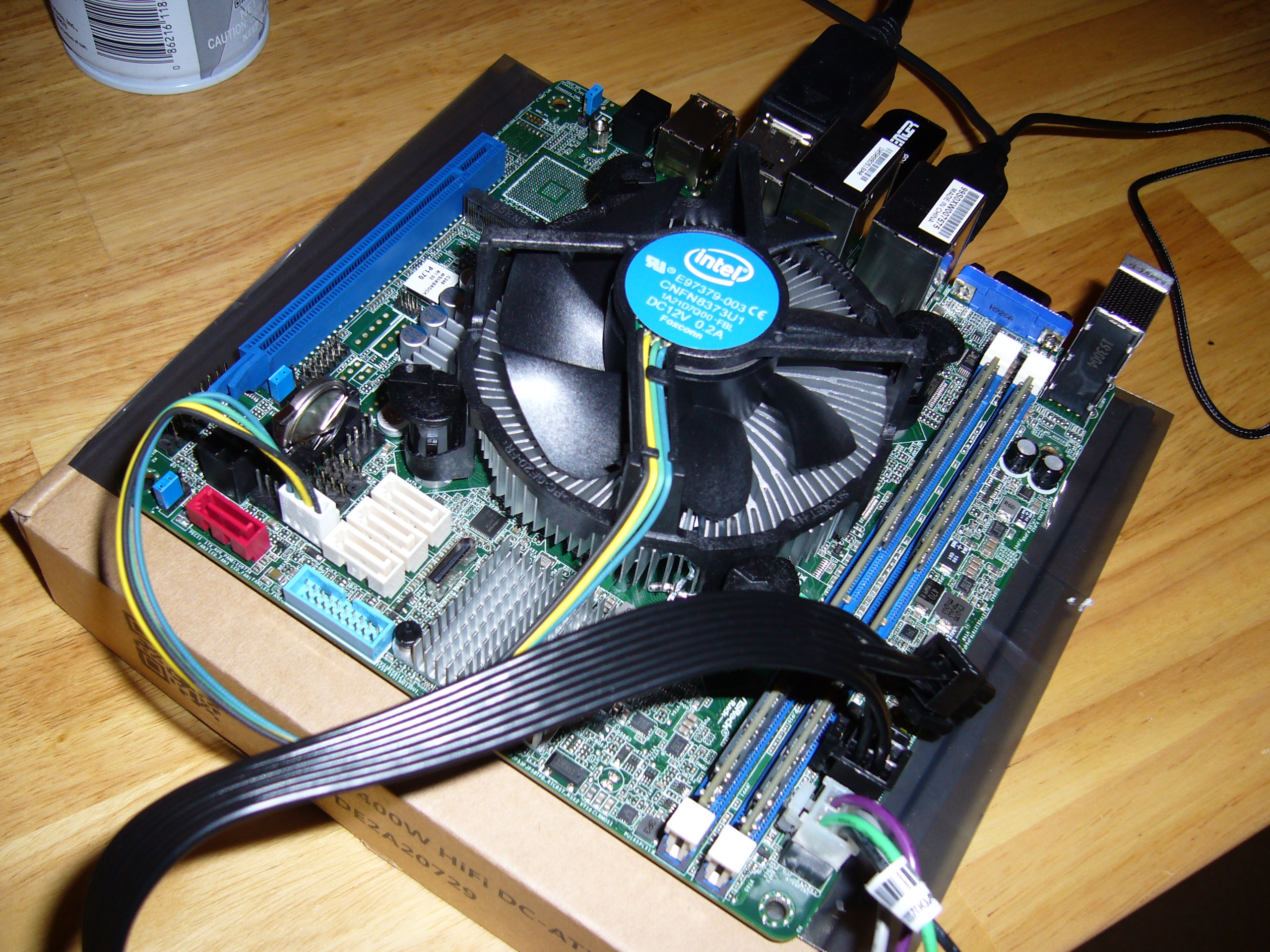
 The motherboard is a Mini ITX 12V input (not ATX) unit, and it is packed with components. It came with an old (2018) BIOS, so I had to borrow an
i3-8350K from another board to upgrade this one to support the i3-9300T.
The motherboard is a Mini ITX 12V input (not ATX) unit, and it is packed with components. It came with an old (2018) BIOS, so I had to borrow an
i3-8350K from another board to upgrade this one to support the i3-9300T.
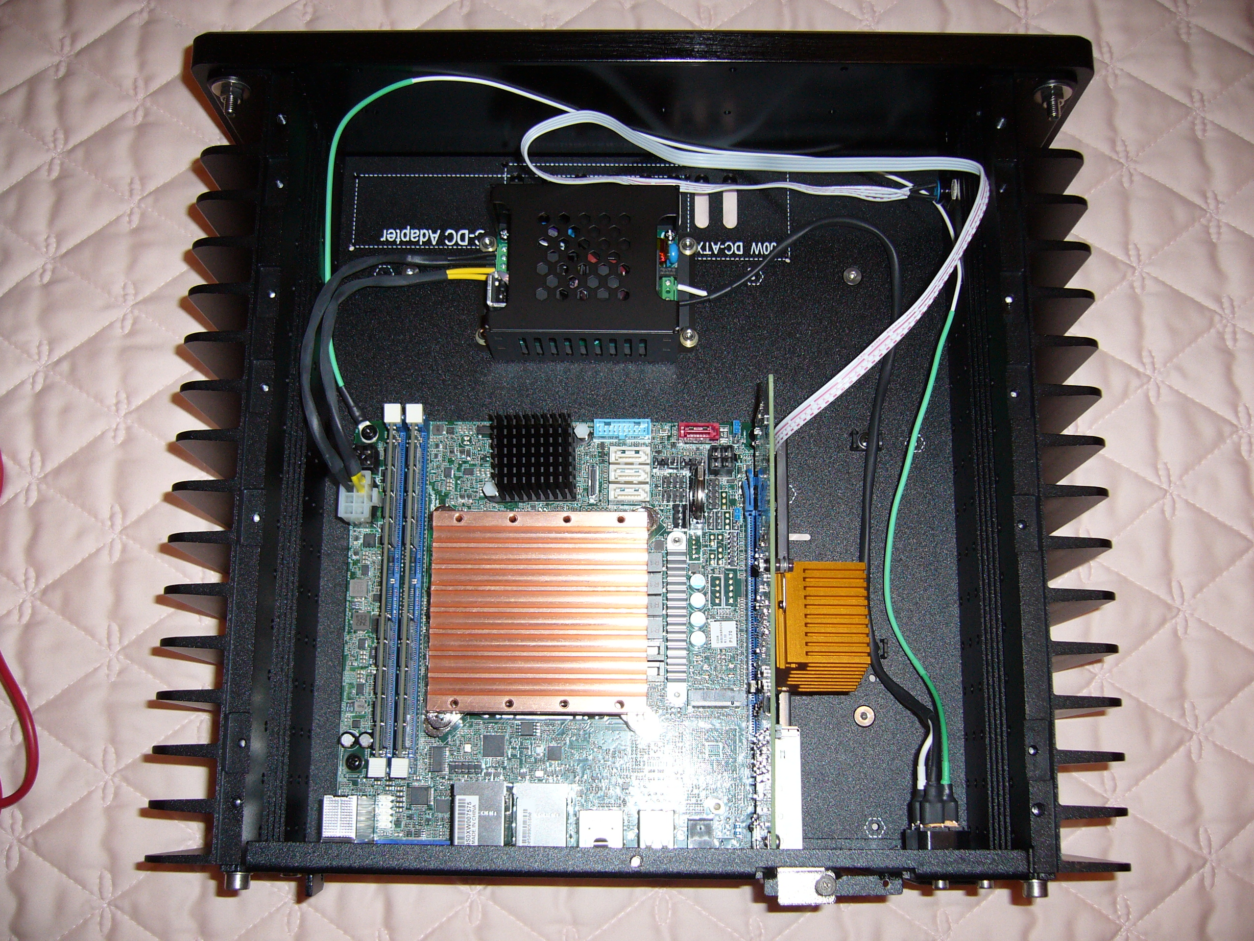
Note the location of the DIMM sockets. I used VLP DIMMs to clear the heat pipes, and they were a pain in the ass to obtain.
 I believe this is with the i3-8350K...
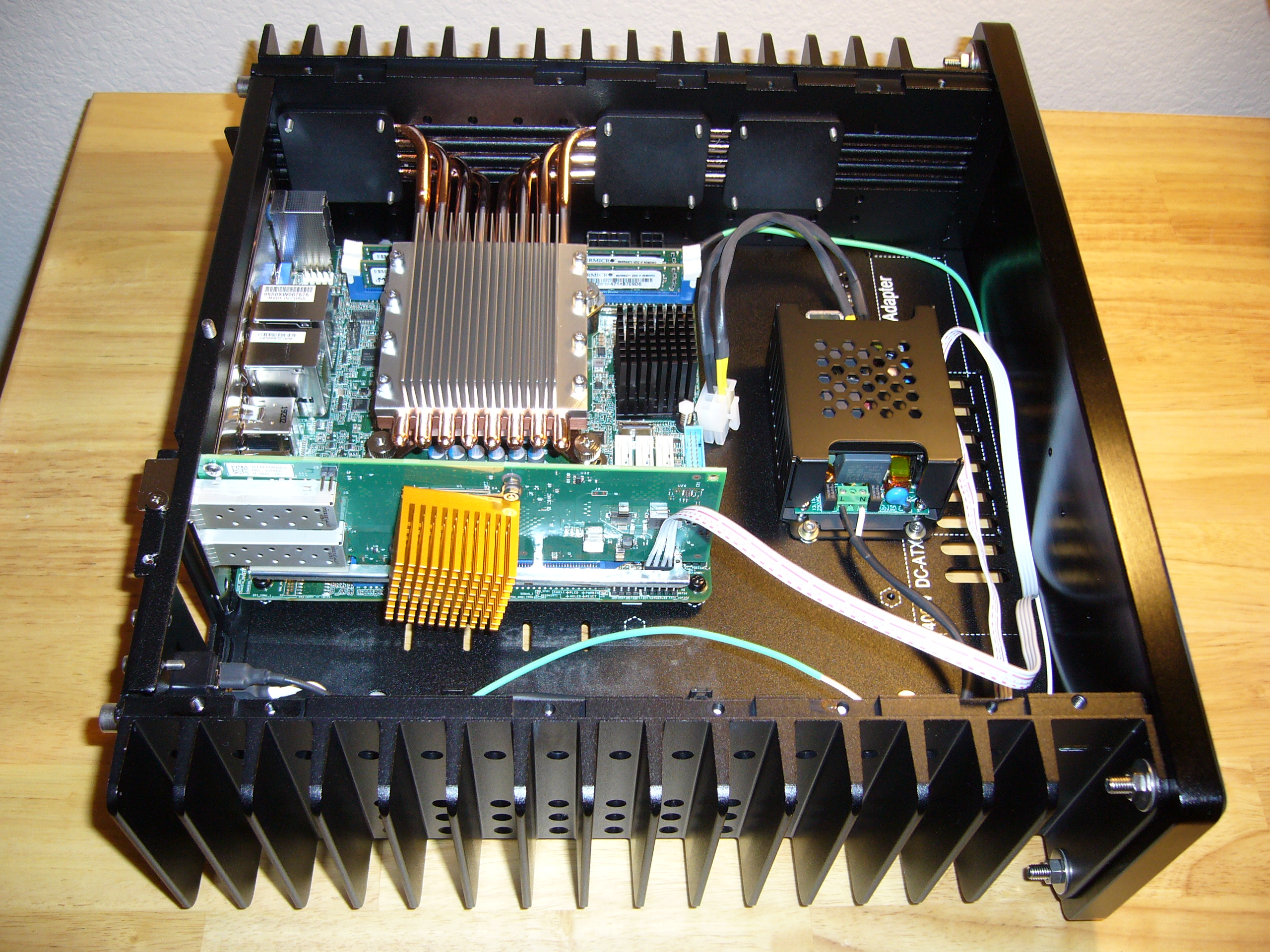
 ...And this is with the i3-9300T. I don't recall why I switched to the Noctua heat sink from the Intel.
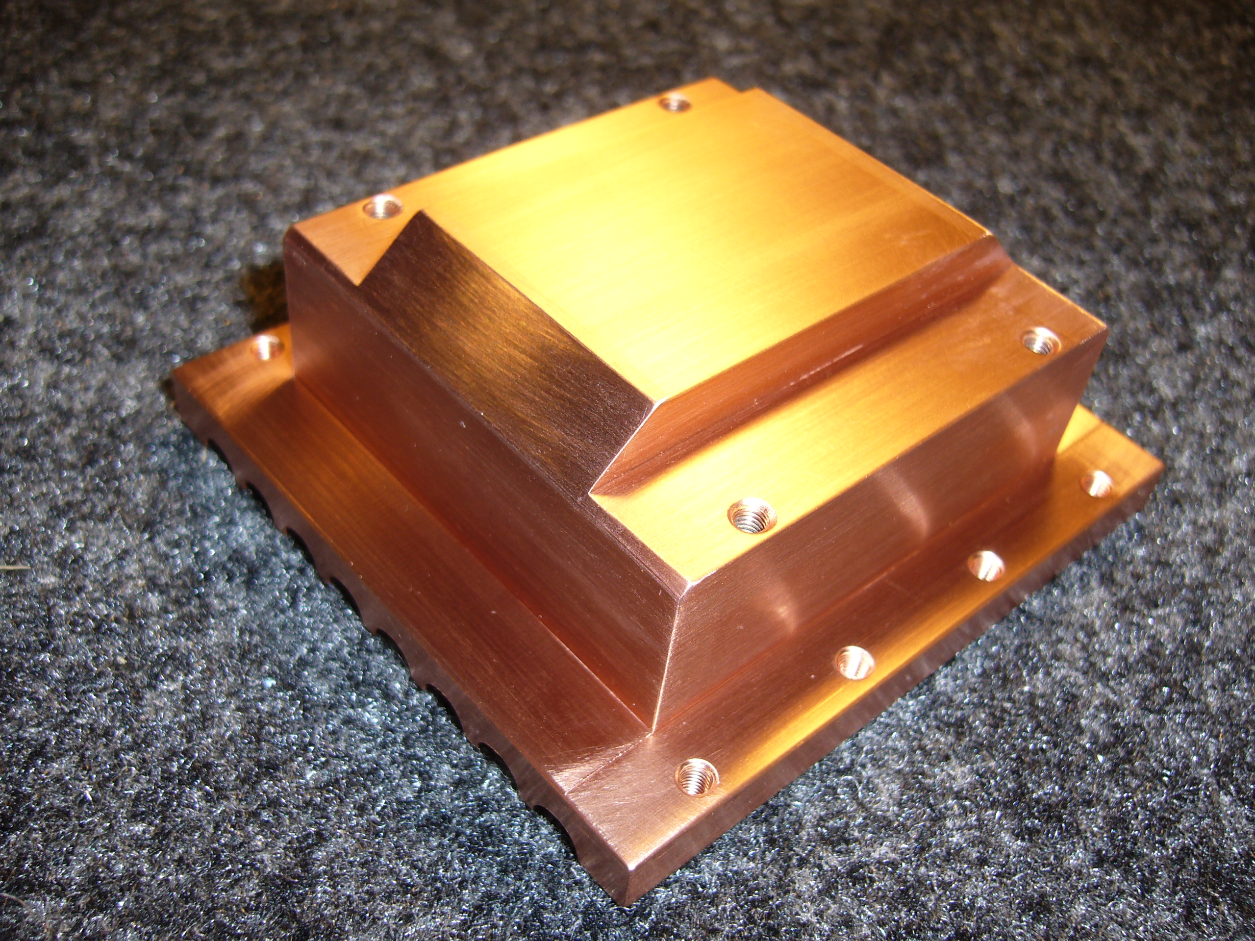
 Here is HDPlex's new CPU block, a kg worth of solid copper wackiness. The lower projections are about 80mm end-to-end; they made contact with the
CPU voltage regulator and came within a whisker of the DIMMs.
Here is HDPlex's new CPU block, a kg worth of solid copper wackiness. The lower projections are about 80mm end-to-end; they made contact with the
CPU voltage regulator and came within a whisker of the DIMMs.
 And here it is after a bit of work with a hacksaw, files, and sandpaper. Now it fits.
The H3v3 kit came with a really lousy combination AMD/Intel backplate, so I used a nice Noctua that I had lying around. The Noctua spacers (black, for Intel) and thumbscrews worked, as well.
 Who needs heat pipes when you have a kilogram of copper? This lasted quite a bit longer than the Noctua above (if you missed it, look back at the
power cable on the fan) before it started cooking, through sheer mass.
Who needs heat pipes when you have a kilogram of copper? This lasted quite a bit longer than the Noctua above (if you missed it, look back at the
power cable on the fan) before it started cooking, through sheer mass.
Also note that the chipset heat sink has grown a bit. No way I was going to let that slide. This one is a bit smaller than the usual blue Zalman, but this motherboard is so tightly packed, it was the best choice available. At least Asrock used a standard mounting footprint. This C246 runs a bit hotter than I like, but still well within spec - perhaps 60C in a 30C/86F room.
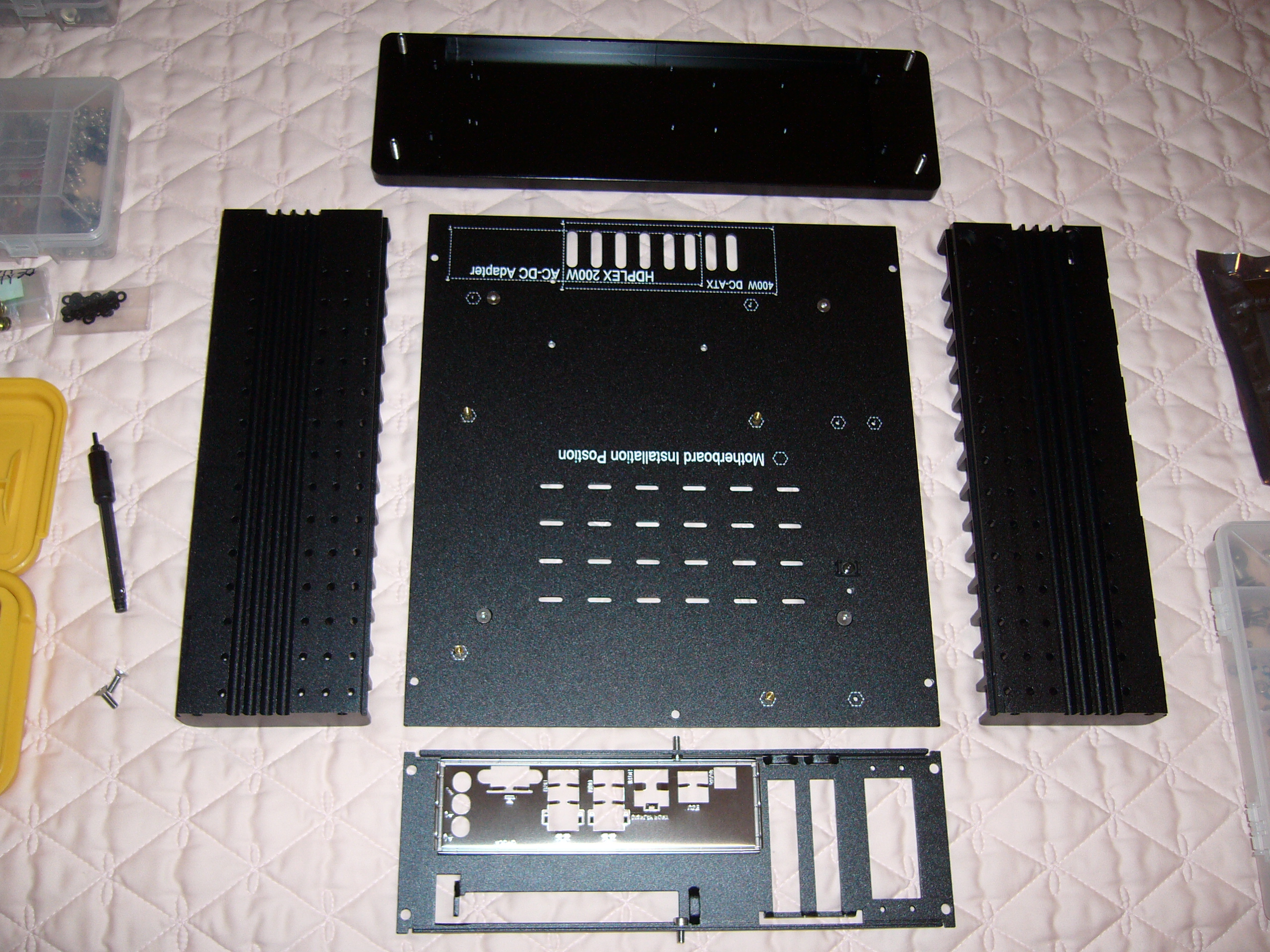
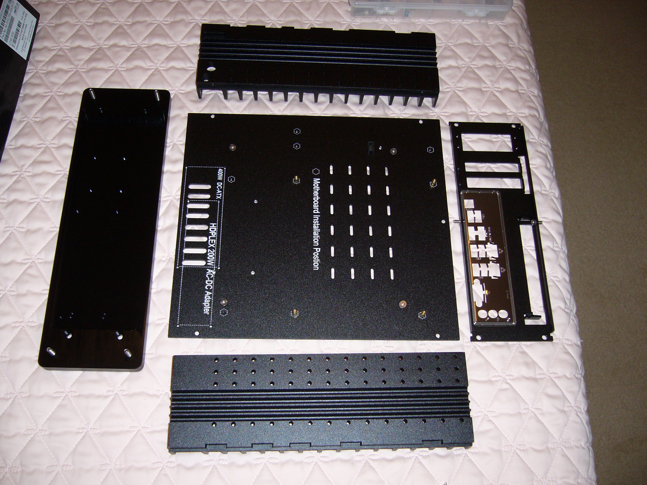
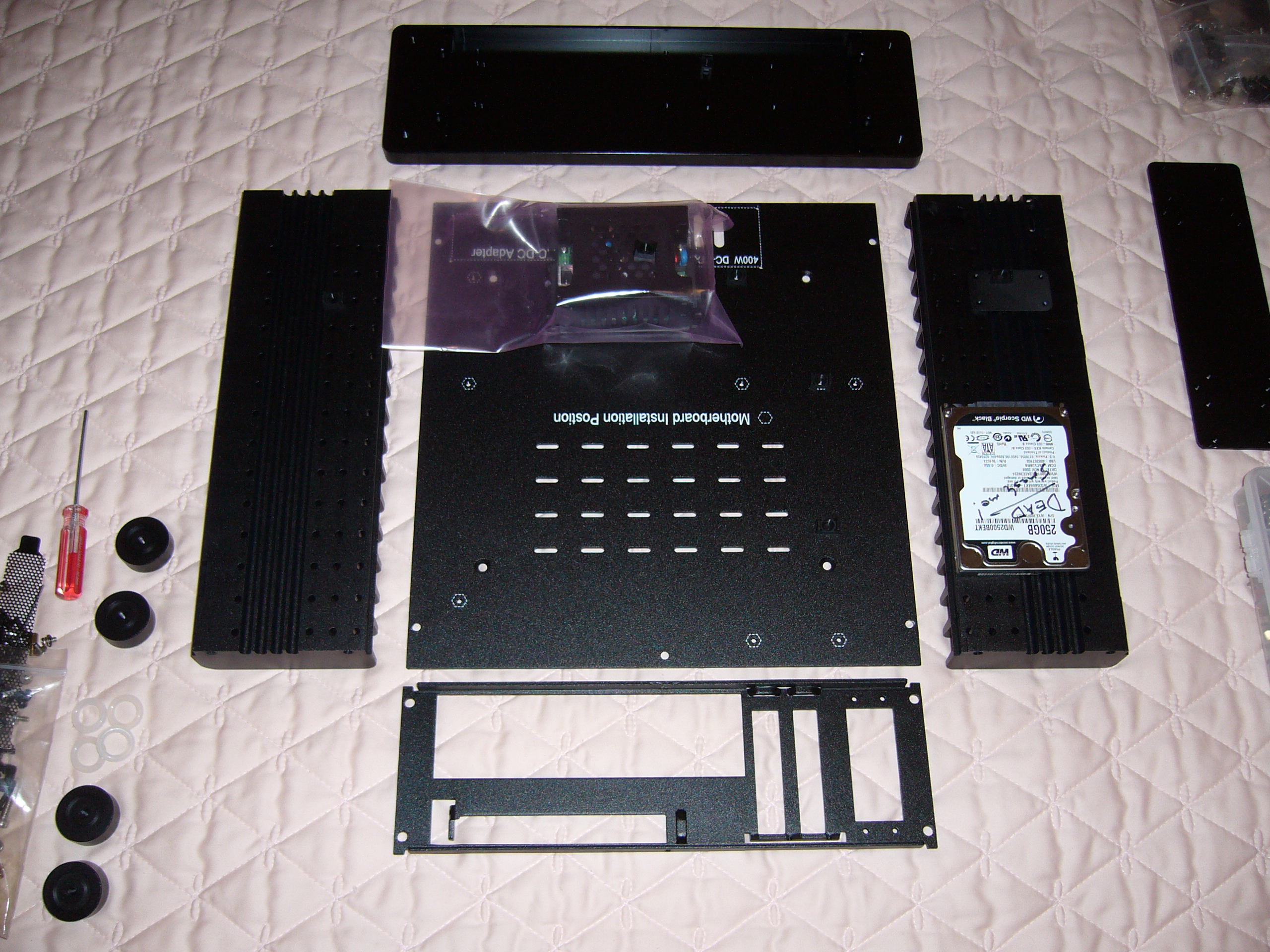 It is always a good idea to lay out your parts, to visualize how everything will fit together. Note the barely-visible mini heat pipe retainer and
cable tie mount on the right heat sink, a bit above the hard drive. As you will see below, I ended up fastening the cable tie mount directly to the
heat sink, as that ended up more in line with the U.2 connector on the SSD.
It is always a good idea to lay out your parts, to visualize how everything will fit together. Note the barely-visible mini heat pipe retainer and
cable tie mount on the right heat sink, a bit above the hard drive. As you will see below, I ended up fastening the cable tie mount directly to the
heat sink, as that ended up more in line with the U.2 connector on the SSD.
 I never did smash that hard drive. Too useful as a template.
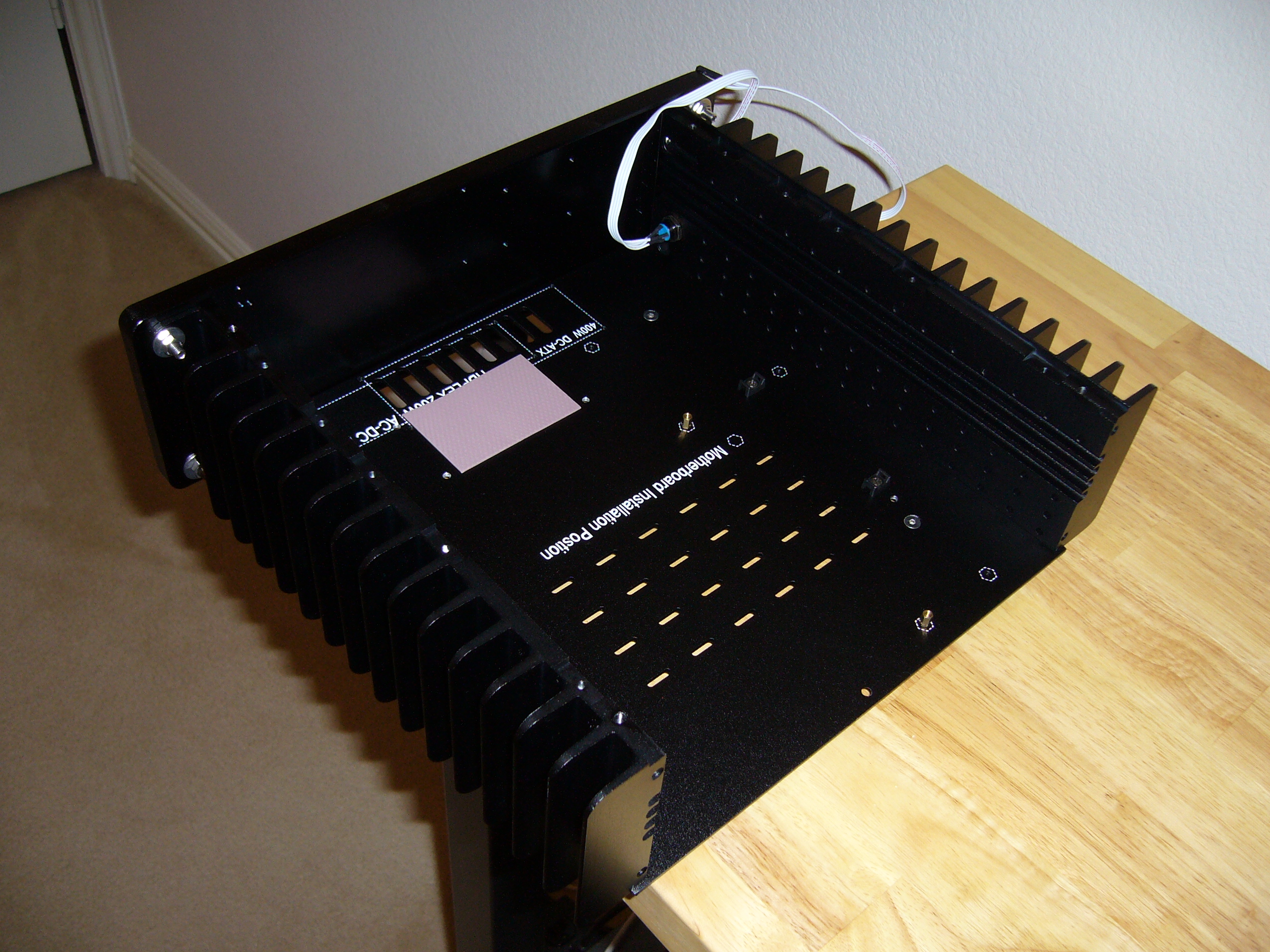
 Here the bottom plate and back plate hardware is in place. The feet screws are Loctited as usual. And I have a cable tie mount already in place.
Oh, and I drilled the holes for the power supply. Only three, as I borrowed one existing hole.
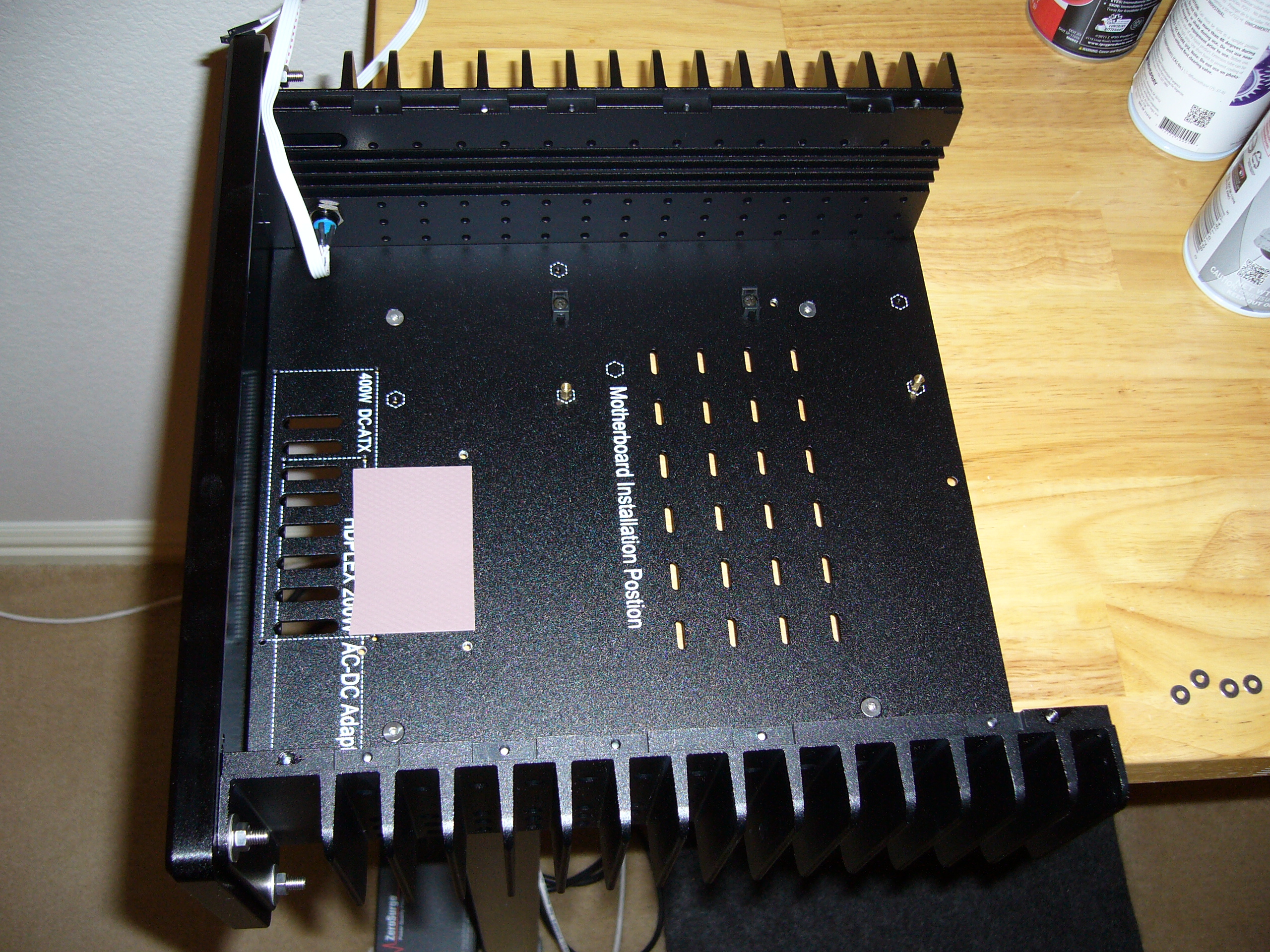
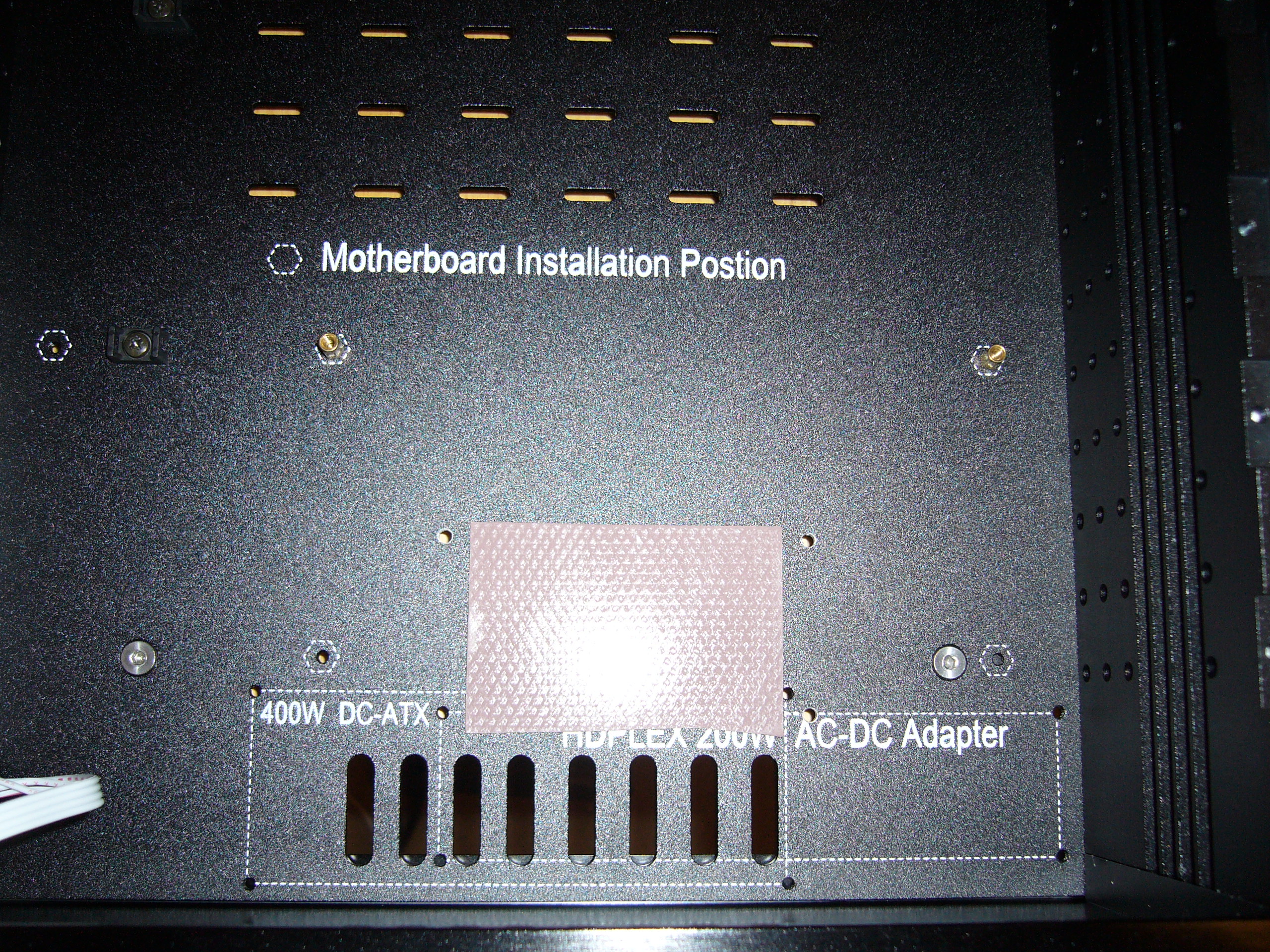
 Placing the power supply thermal pad.
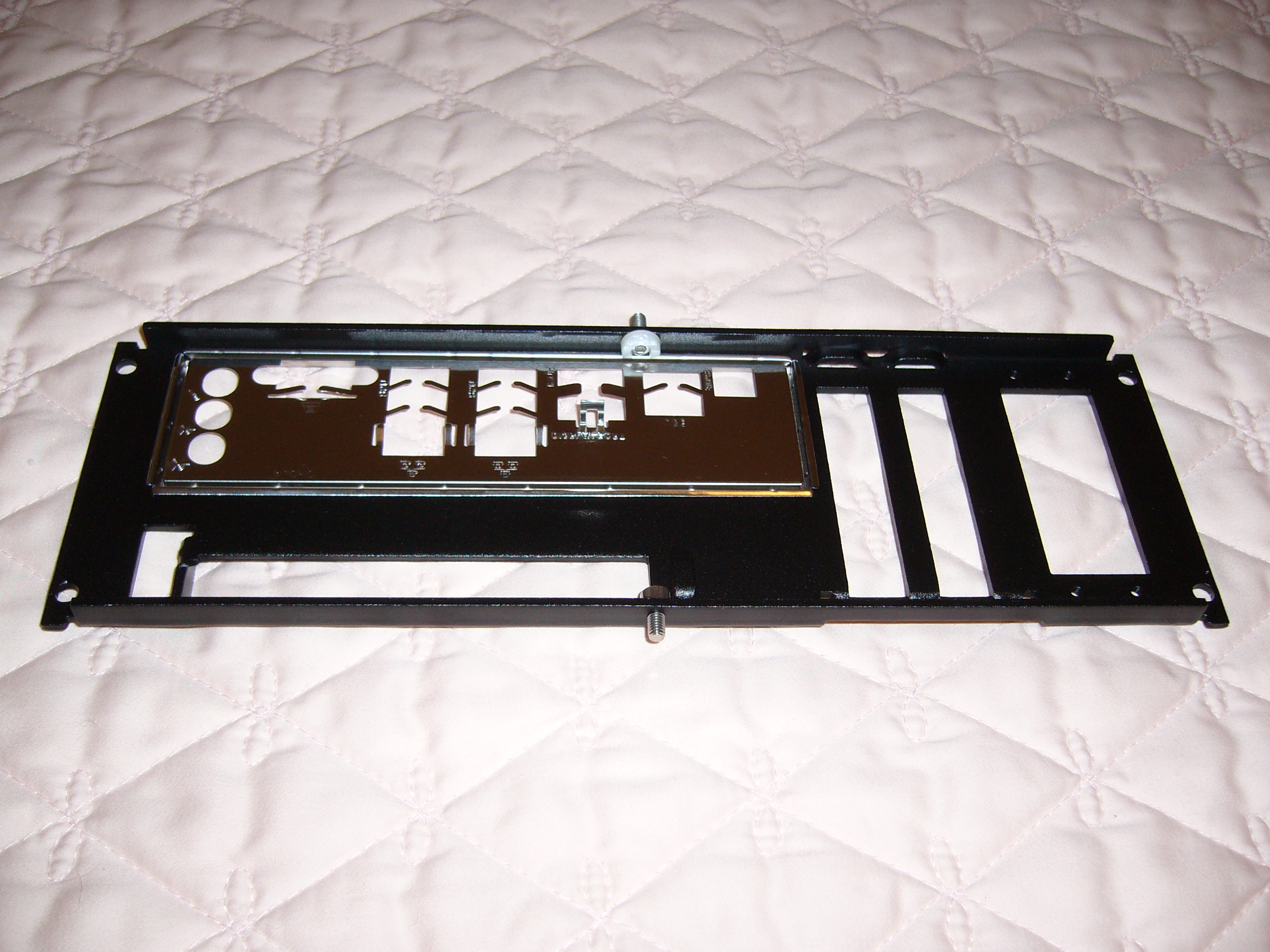
Note that I used my typical method of installing the front panel: set screws Loctited into place, with nuts and washers. This model also has a rather clever reversible arrangment that allows you to add handles (useless) or four additional M5 screws. I chose the latter, so this front panel is on there good.
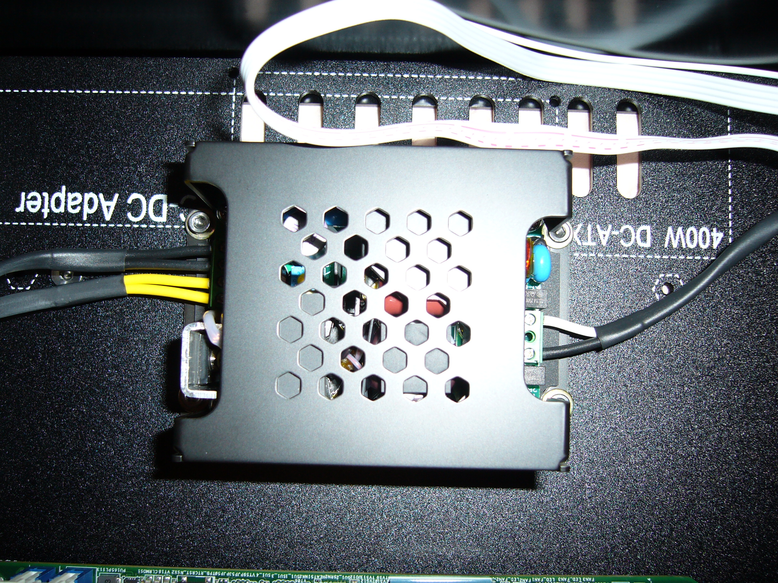
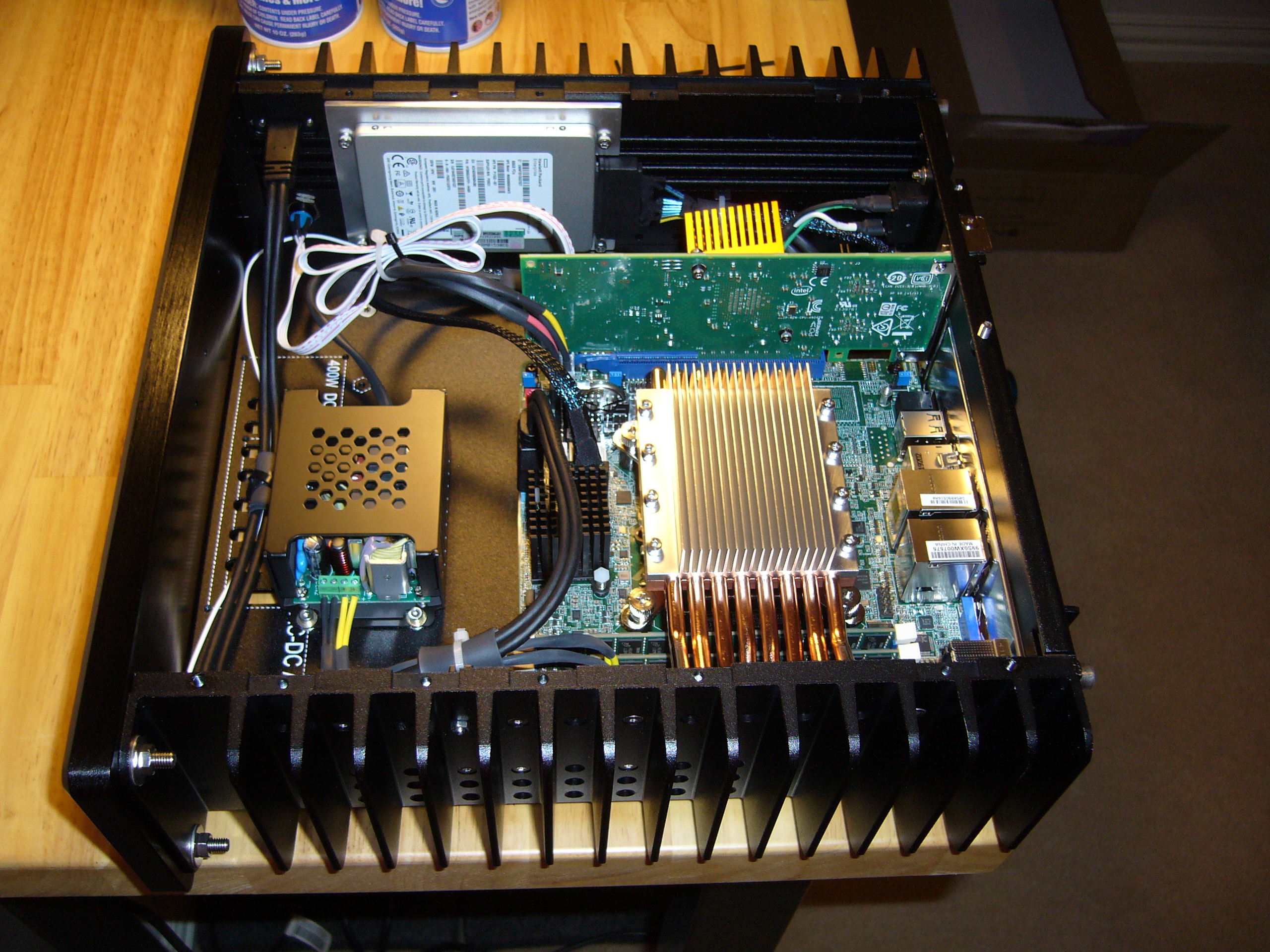
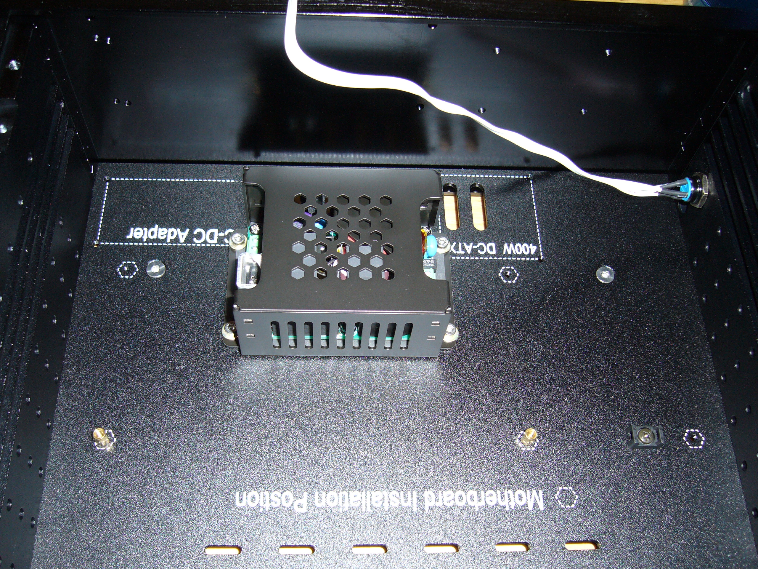 The power supply is a Traco TPP 100-112 12V 100W unit. You can find this design from several manufacturers - I chose the cheapest.
Unfortunately this one runs a bit hot (compared to the big Meanwell in the H5v2), and dumps much of its heat into the interior of the enclosure, rather than into the bottom plate.
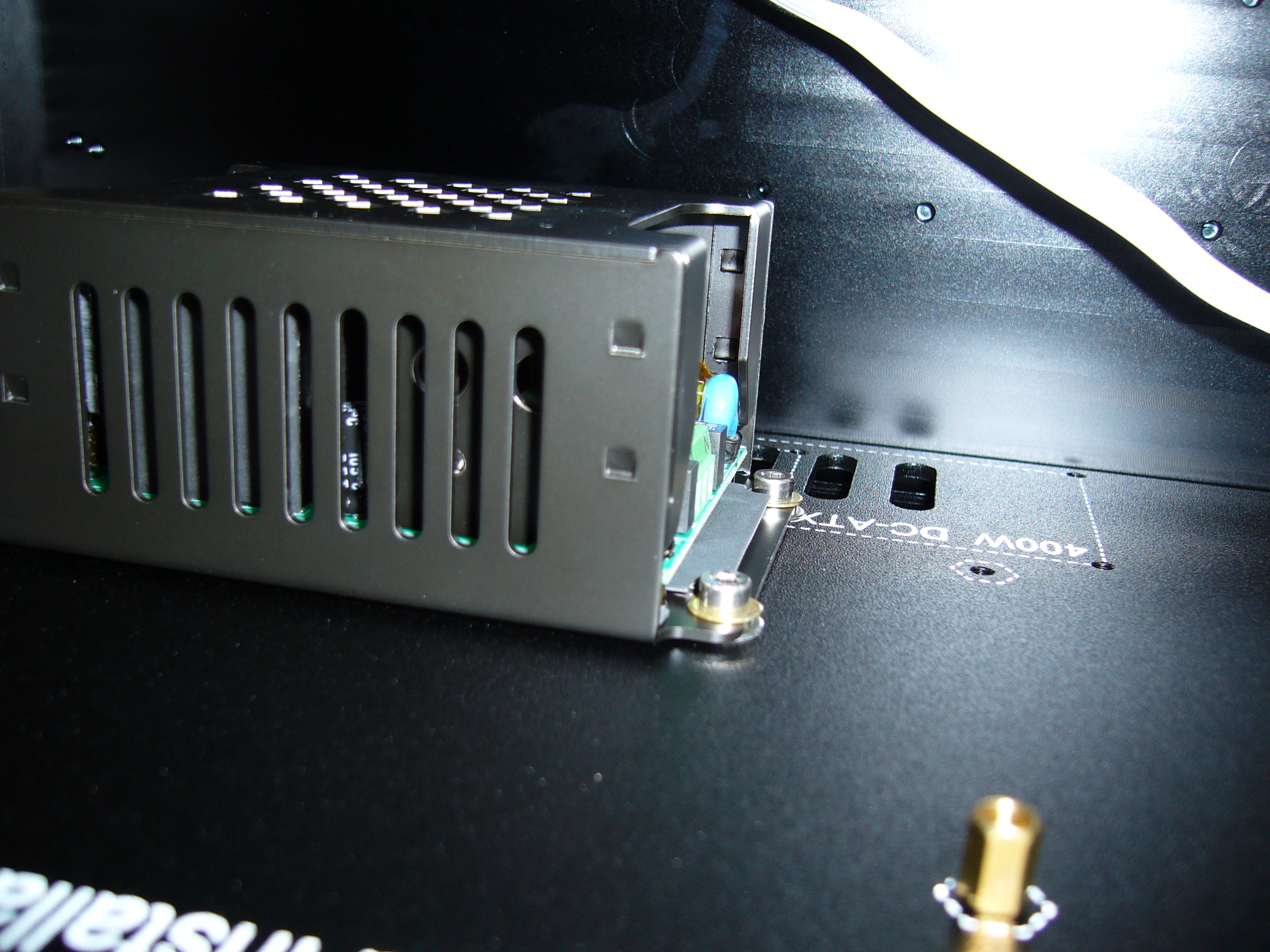 Here you can (kind of) see the mounting hardware arrangement, with washers between the power supply and bottom plate to provide space for the
thermal pad. Getting it all together is pretty fiddly, but secure once done.
Here you can (kind of) see the mounting hardware arrangement, with washers between the power supply and bottom plate to provide space for the
thermal pad. Getting it all together is pretty fiddly, but secure once done.
 Close view of the backplate studs with the lower insulator installed. Same arrangement as on the H5v2.
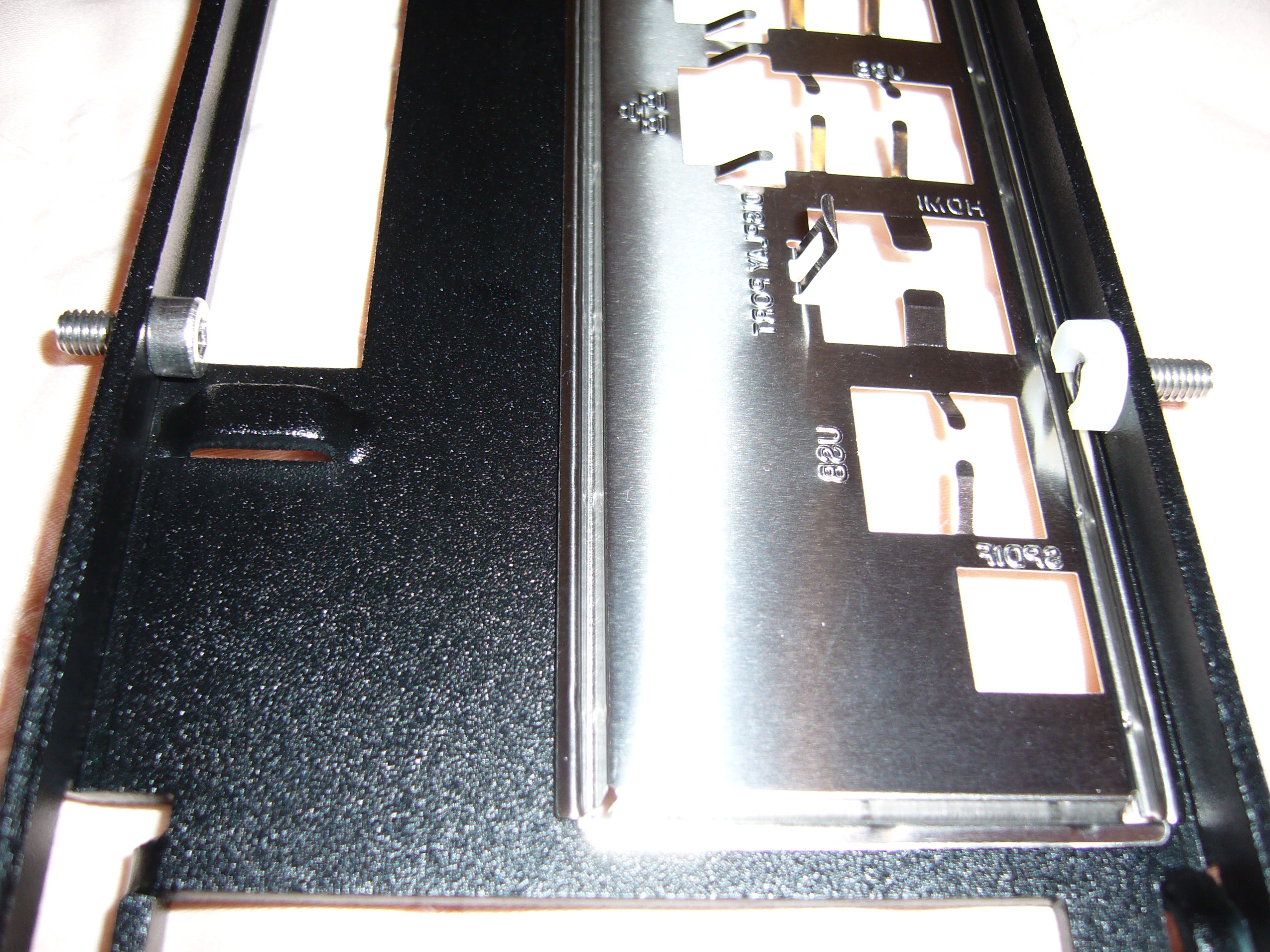
 Heh. Whoever designed this thing picked the perfect spot for the USB C cutout: Right in line with a 5mm tapped hole for a front panel screw.
Brilliant! I found a short screw for that position.
Heh. Whoever designed this thing picked the perfect spot for the USB C cutout: Right in line with a 5mm tapped hole for a front panel screw.
Brilliant! I found a short screw for that position.
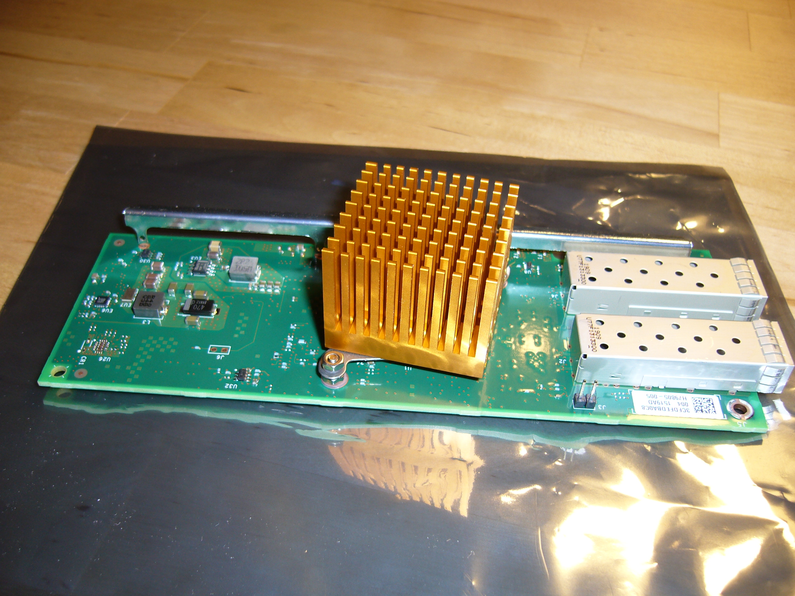
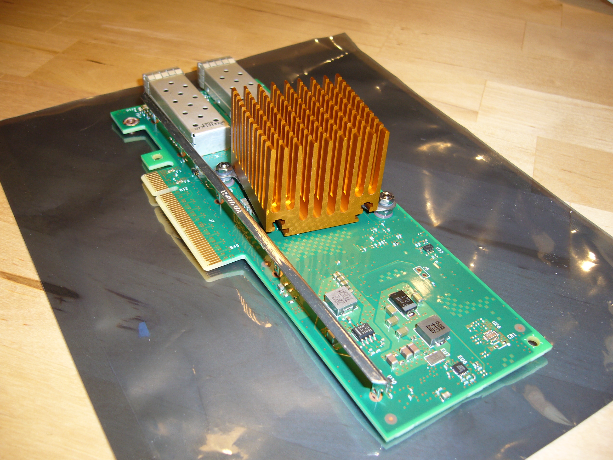
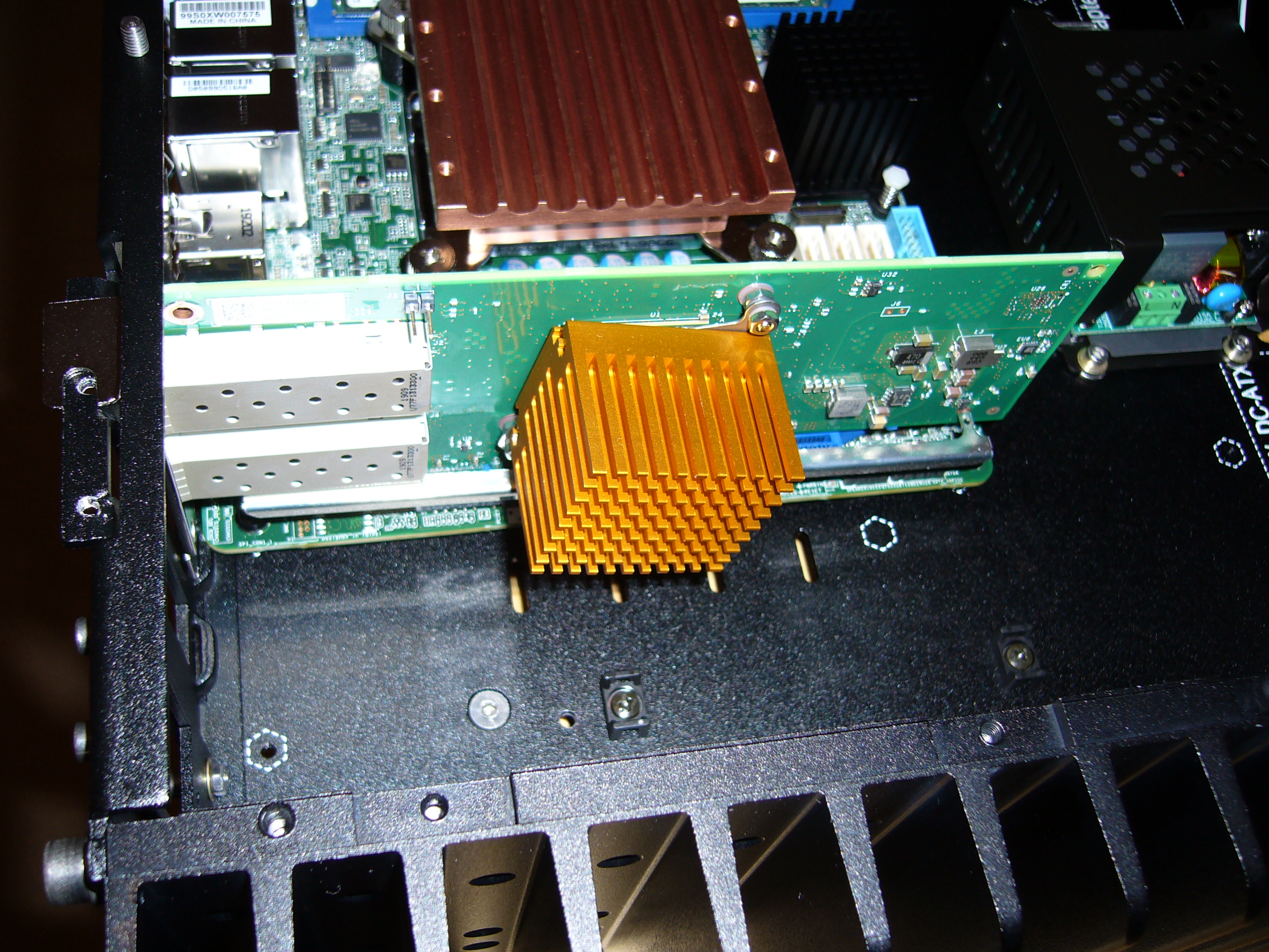
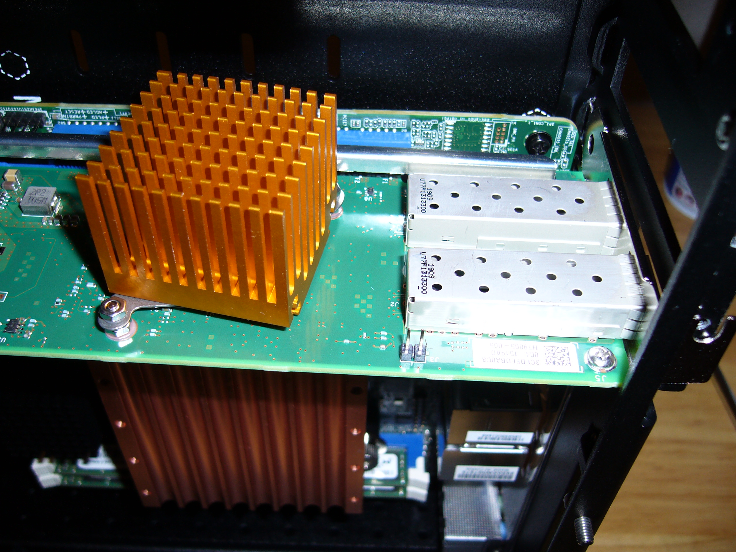
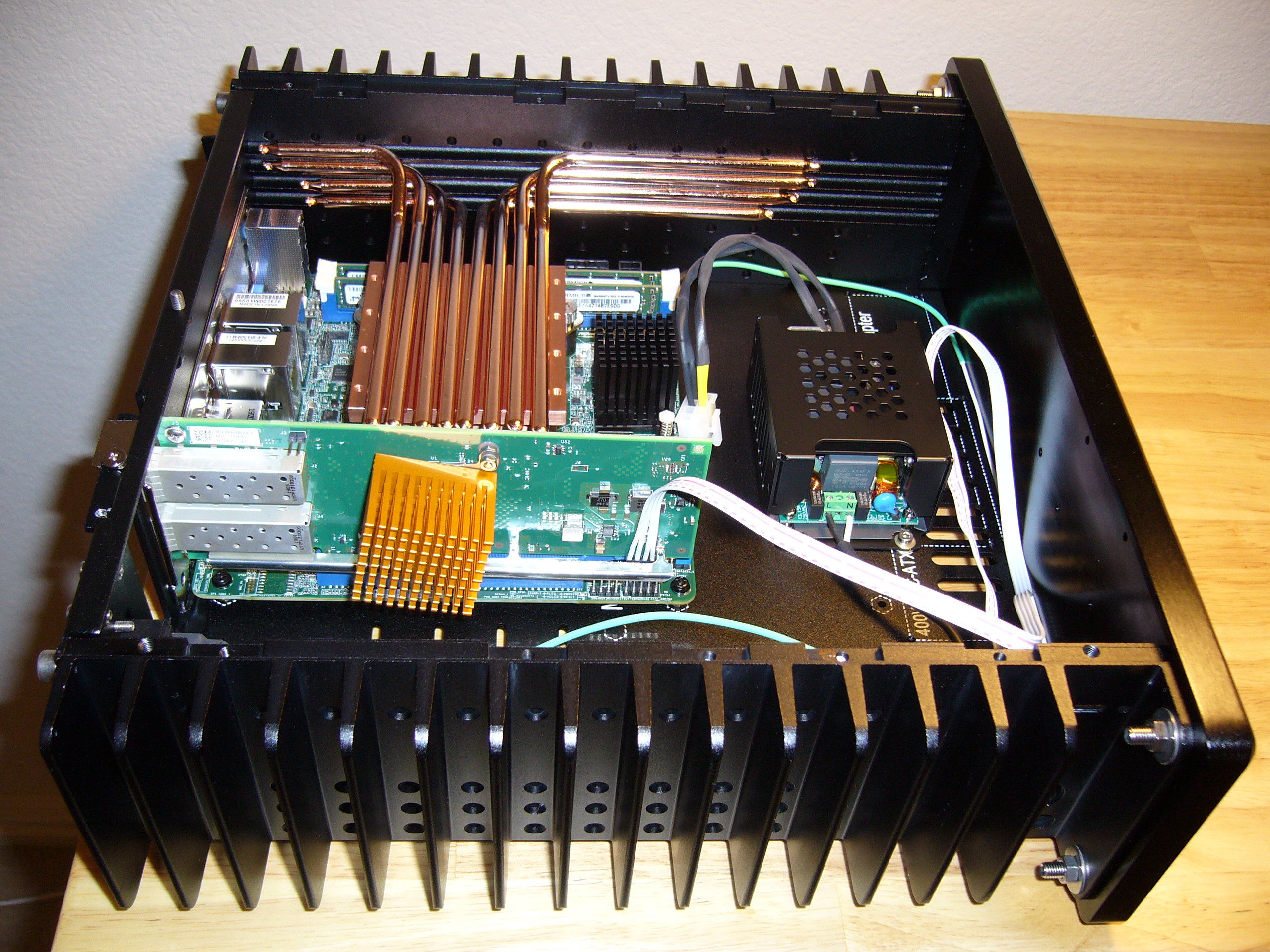
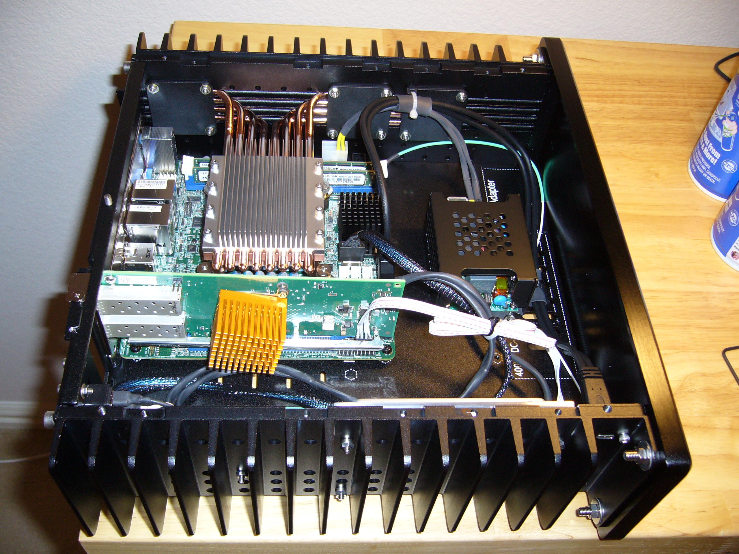
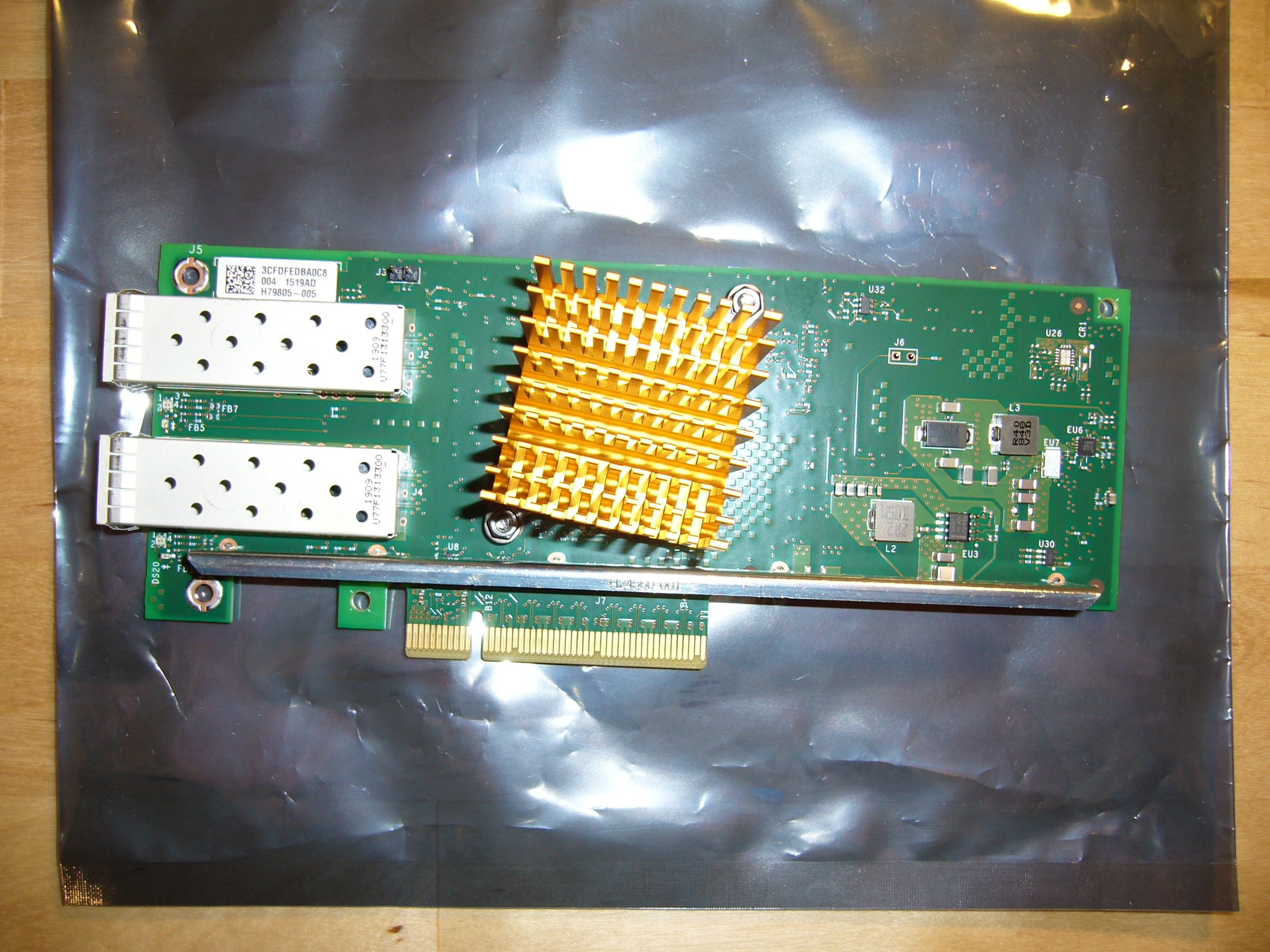 Naturally I had to upgrade the heat sink on the X710 (dual SFP+ 10Gb Ethernet). I chose the smaller gold Zalman due to space limitations, and I'm
glad I did.
Naturally I had to upgrade the heat sink on the X710 (dual SFP+ 10Gb Ethernet). I chose the smaller gold Zalman due to space limitations, and I'm
glad I did.
If anyone is looking, I believe I transferred the whatever-the-hell-it-is-mark hologram sticker to the clamshell or manual. They never place the things properly, and flappy loose stickers offend me.
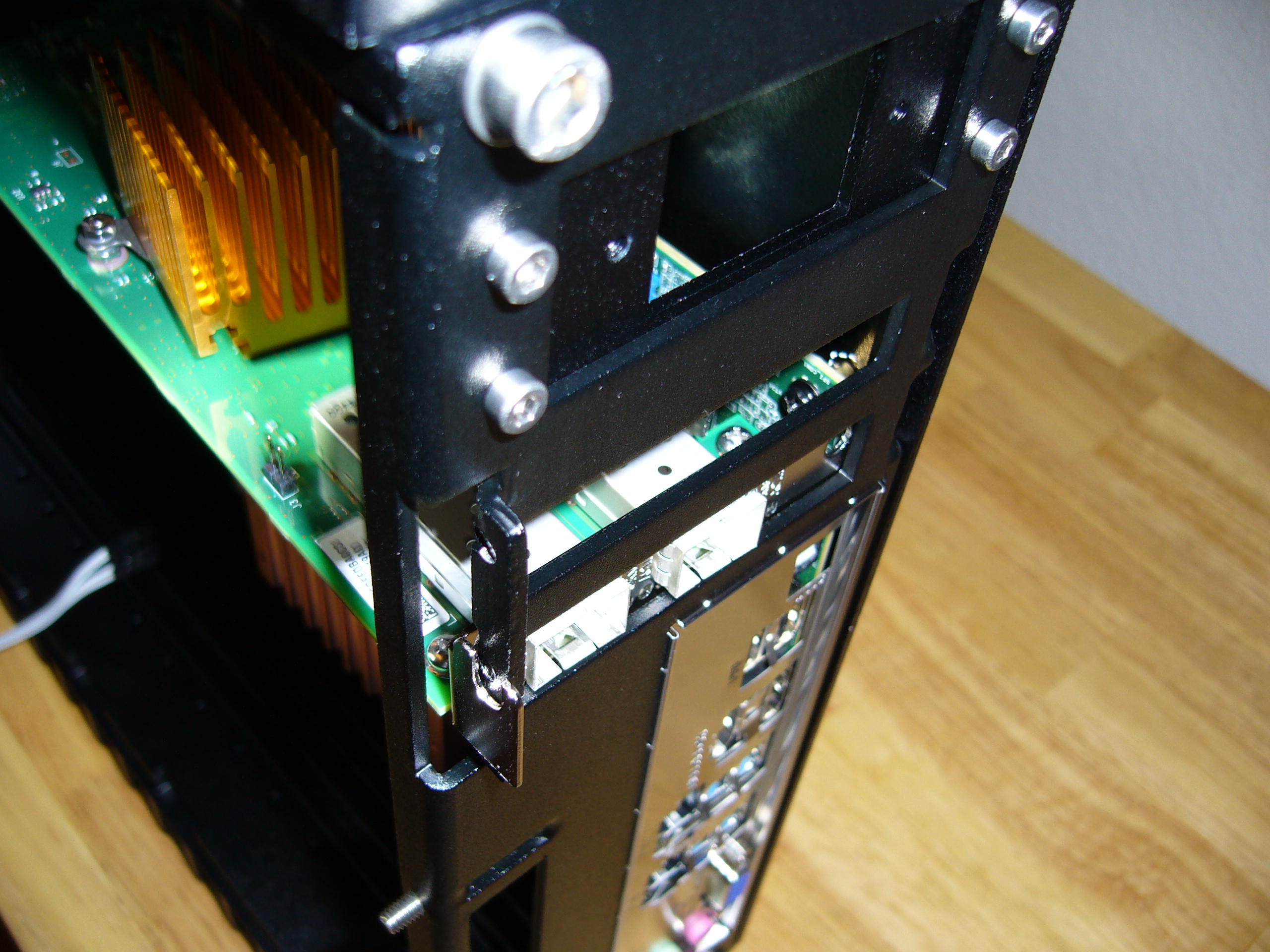
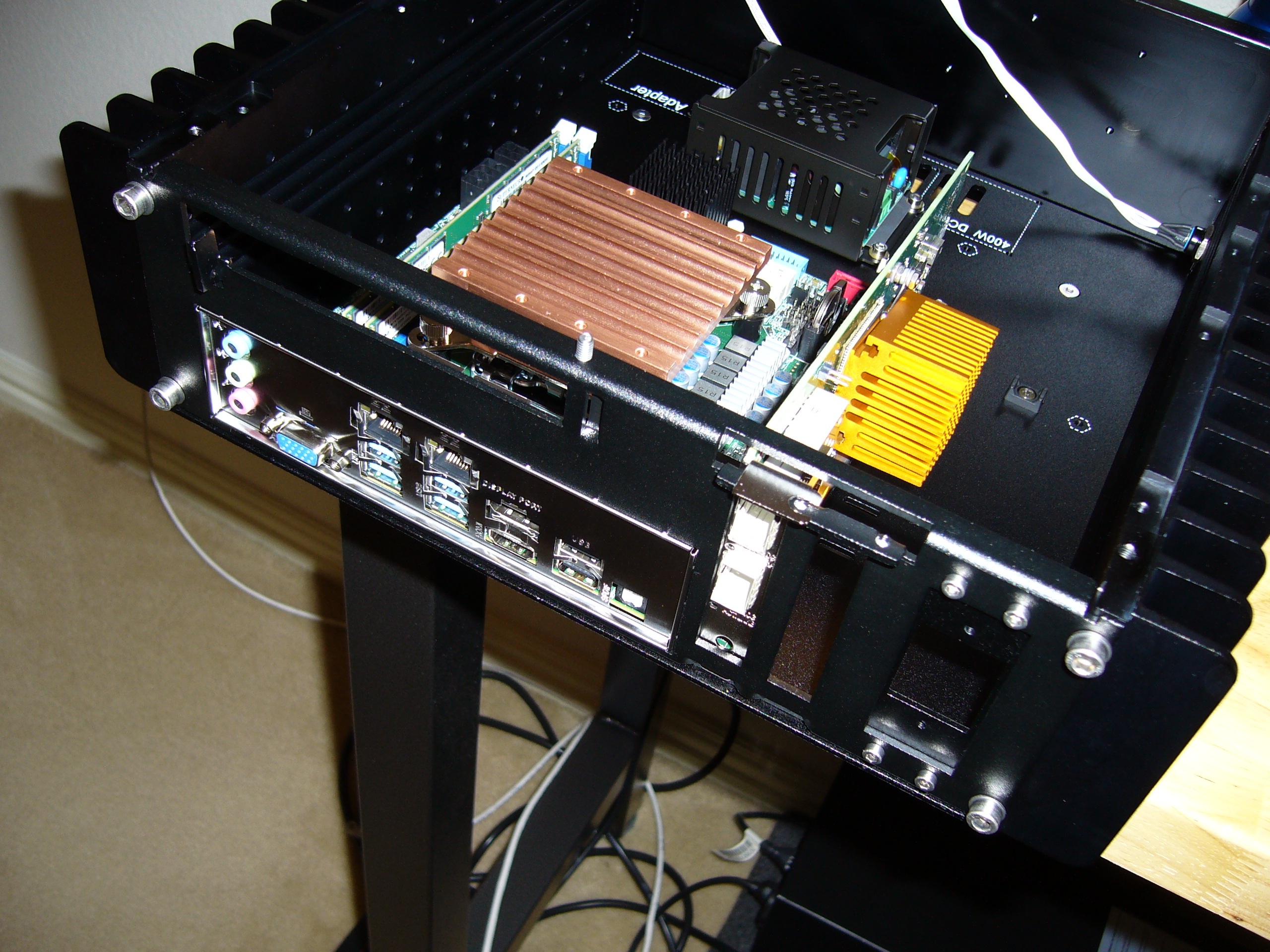 Installing the X710 was a nightmare. Looking at it, there seems to be plenty of space to work, but looks can be deceiving... There's just no
clearance around it to fit tools. I was turning a screwdriver to tighten the bracket screws by sticking a couple fingers through the power entry.
Nuts. That's never coming out.
Installing the X710 was a nightmare. Looking at it, there seems to be plenty of space to work, but looks can be deceiving... There's just no
clearance around it to fit tools. I was turning a screwdriver to tighten the bracket screws by sticking a couple fingers through the power entry.
Nuts. That's never coming out.
I do not believe I had to flatten the top mounting surface on the X710's bracket - it was stamped flat from the factory. I have an older 82599/X520, and its bracket has the usual divot stamped in the top mounting surface.
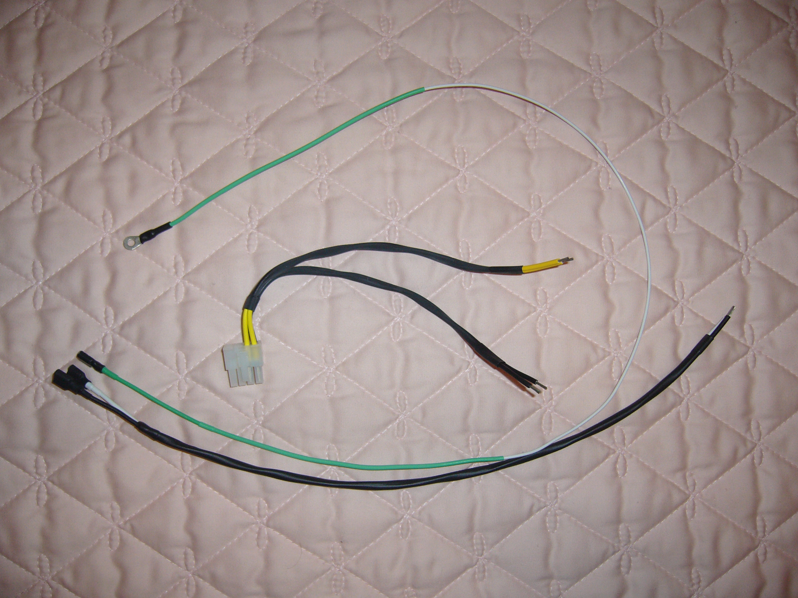 Power cabling for the Traco and motherboard. Note that this model power supply used screw terminals. I would choose plug-in terminals in the future.
 Check the H5v2 page for heat pipe layout comments.
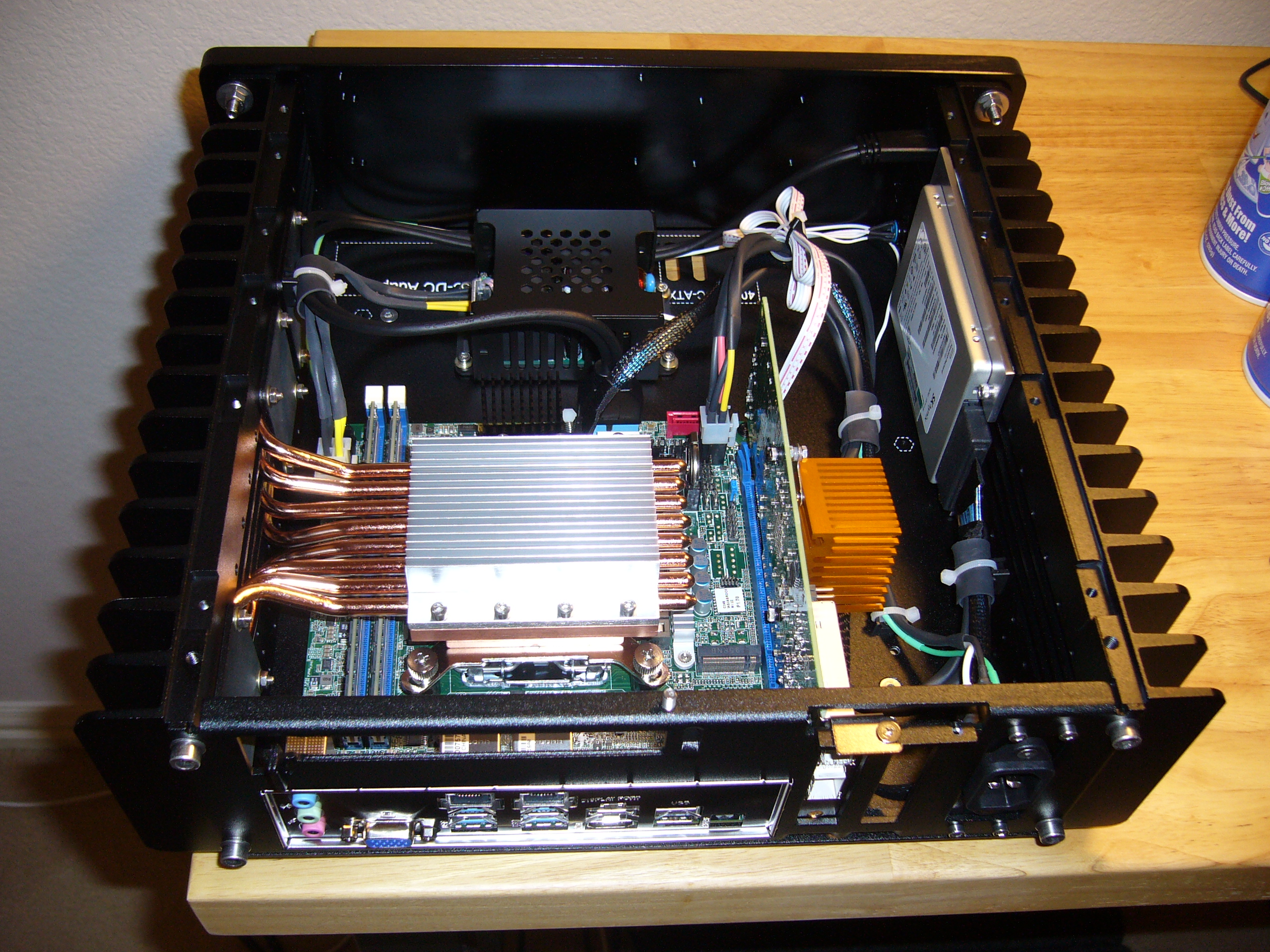
One unusual aspect to this installation is the short distance between the CPU socket and the back of the board. I was not sure I could fit the heat pipes in a standard order, but they fit fine, as you can see.
The other unusual aspect is the DIMM location, as I said earlier. The VLP DIMMs fit fine as well. I do not know that I have a photograph here that illustrates this, but standard-height DIMMs will most definitely not fit.
Side silly note: Look at where I had to route the front panel cable. Yep, through the X710's stiffener. It's a miracle, but it fits.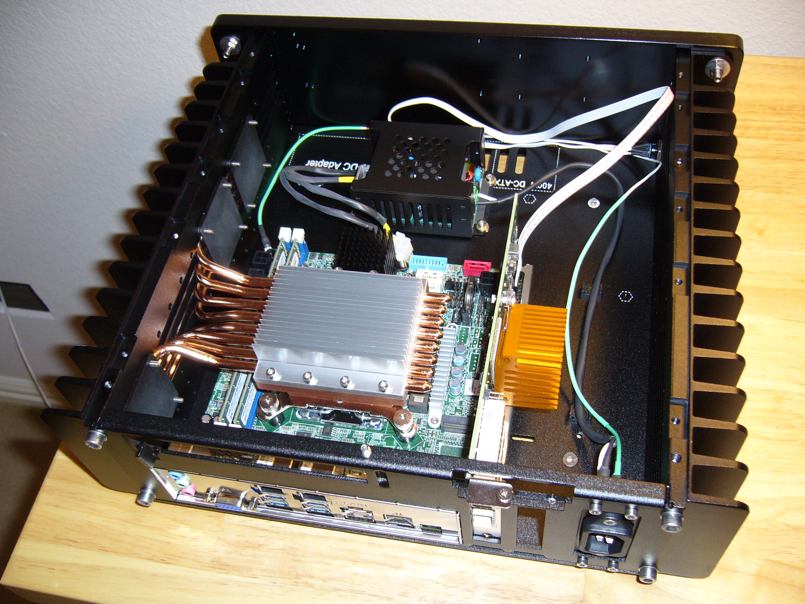
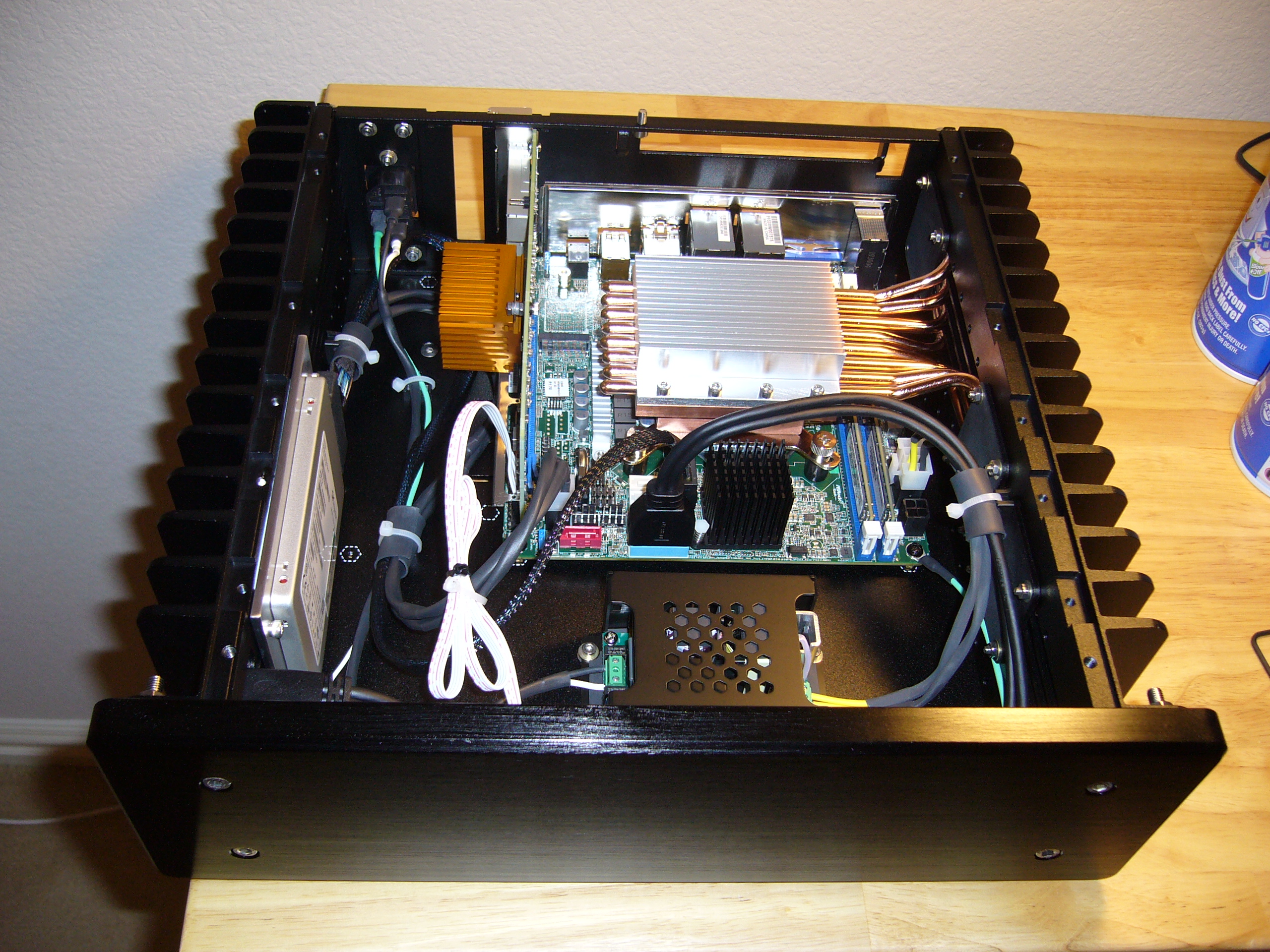
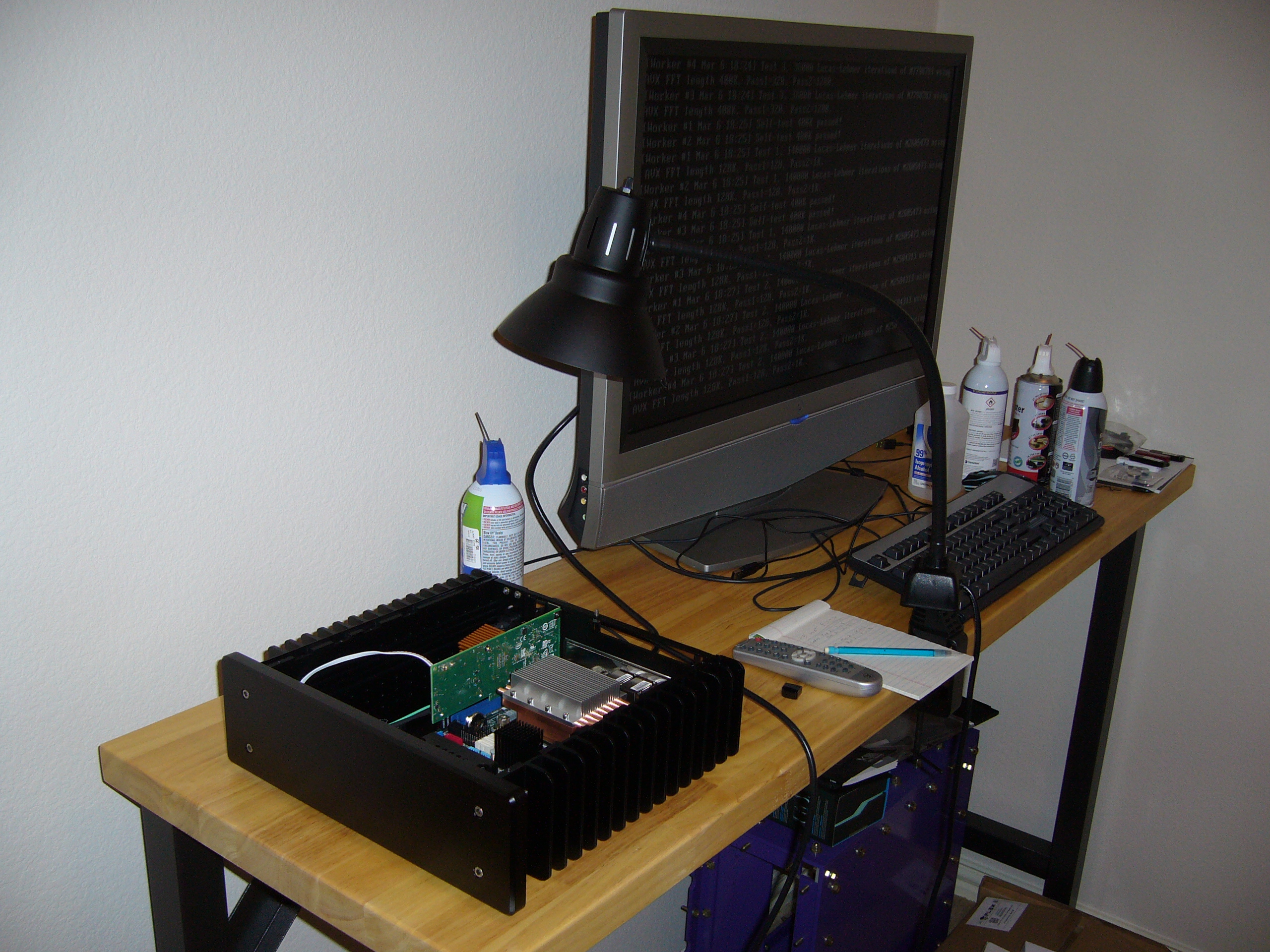 Time to see if it all catches fire...
Incidentally, GIMPS (mprime/Prime95) does not work the non-hyperthreading Core i3s particularly hard. My two systems (the H5v2 and this H3v3) get about as hot running MemTest86. Oh, this one does run hotter than my H5v2. Smaller heat sink and slightly higher clock.
A bit of a surprise was the CPU voltage regulator on this board: it gets only slightly warm. So the Gigabyte board in the H5v2 has a cool chipset and hot regulator, and this has the opposite.
This photo also reveals my canned air addiction. I don't huff the stuff intentionally...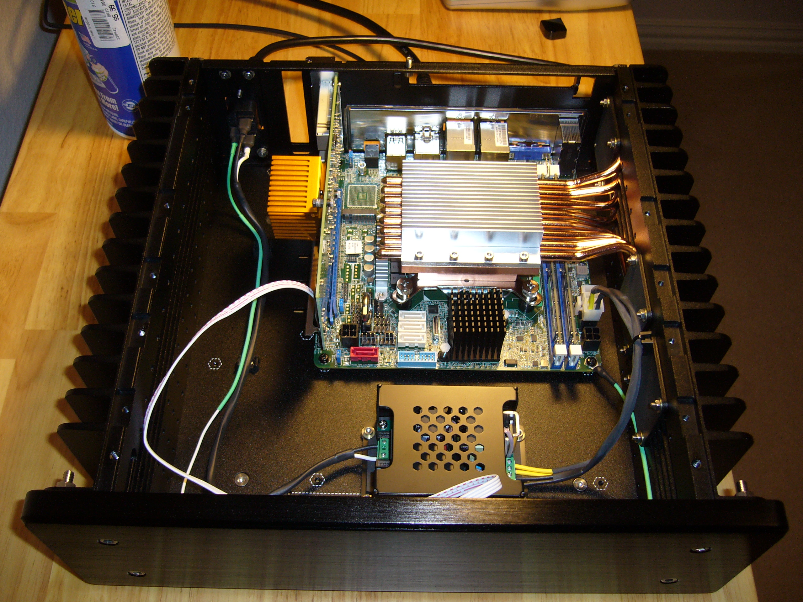 Speaking of tight spaces, look into the upper right corner of the enclosure, at the heat pipe retainer next to the audio jacks... Yep, I wasn't
getting a nut on that one.
Speaking of tight spaces, look into the upper right corner of the enclosure, at the heat pipe retainer next to the audio jacks... Yep, I wasn't
getting a nut on that one.
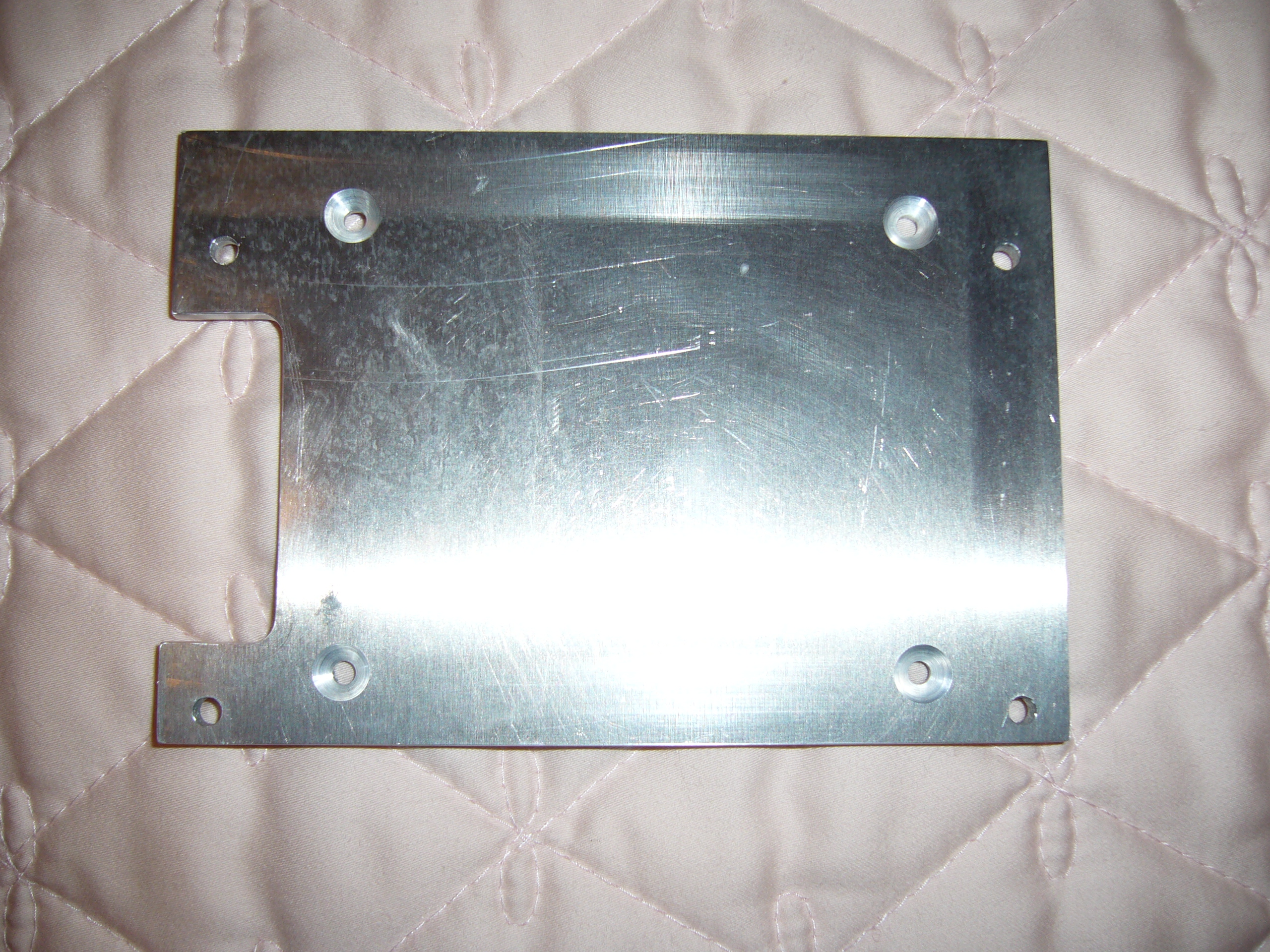 Here is the plate I whipped up to adapt a 2.5" SSD to the HDPlex heat sink. I screwed this thing up multiple times, from not considering screw head
dimensions to having a countersink go wild and make a giant oblong hole. (Get HTC countersinks to avoid that one.) The finish on this one may be a
bit lacking... I got pretty tired of making these.
Here is the plate I whipped up to adapt a 2.5" SSD to the HDPlex heat sink. I screwed this thing up multiple times, from not considering screw head
dimensions to having a countersink go wild and make a giant oblong hole. (Get HTC countersinks to avoid that one.) The finish on this one may be a
bit lacking... I got pretty tired of making these.
The giant notch provides clearance for the U.2 cable. It occupies space below the bottom surface of the device. Be aware of that possibility if you fabricate something similar.
 Complete. The SSD is an SK Hynix PE6031. The cable is (I believe) a Supermicro CBL-SAST-0956 OCuLink to U.2. Oddly enough, it all worked.
This SSD is a 12W device, as opposed to 5-6W from most M.2 devices. Attached through a heat spreader (with thermal compound) to a large heat sink (with thermal pads), it runs quite cool. Note that only smooth-bottomed SSDs are appropriate for this type of installation, unless you care to dismount the board from its enclosure.
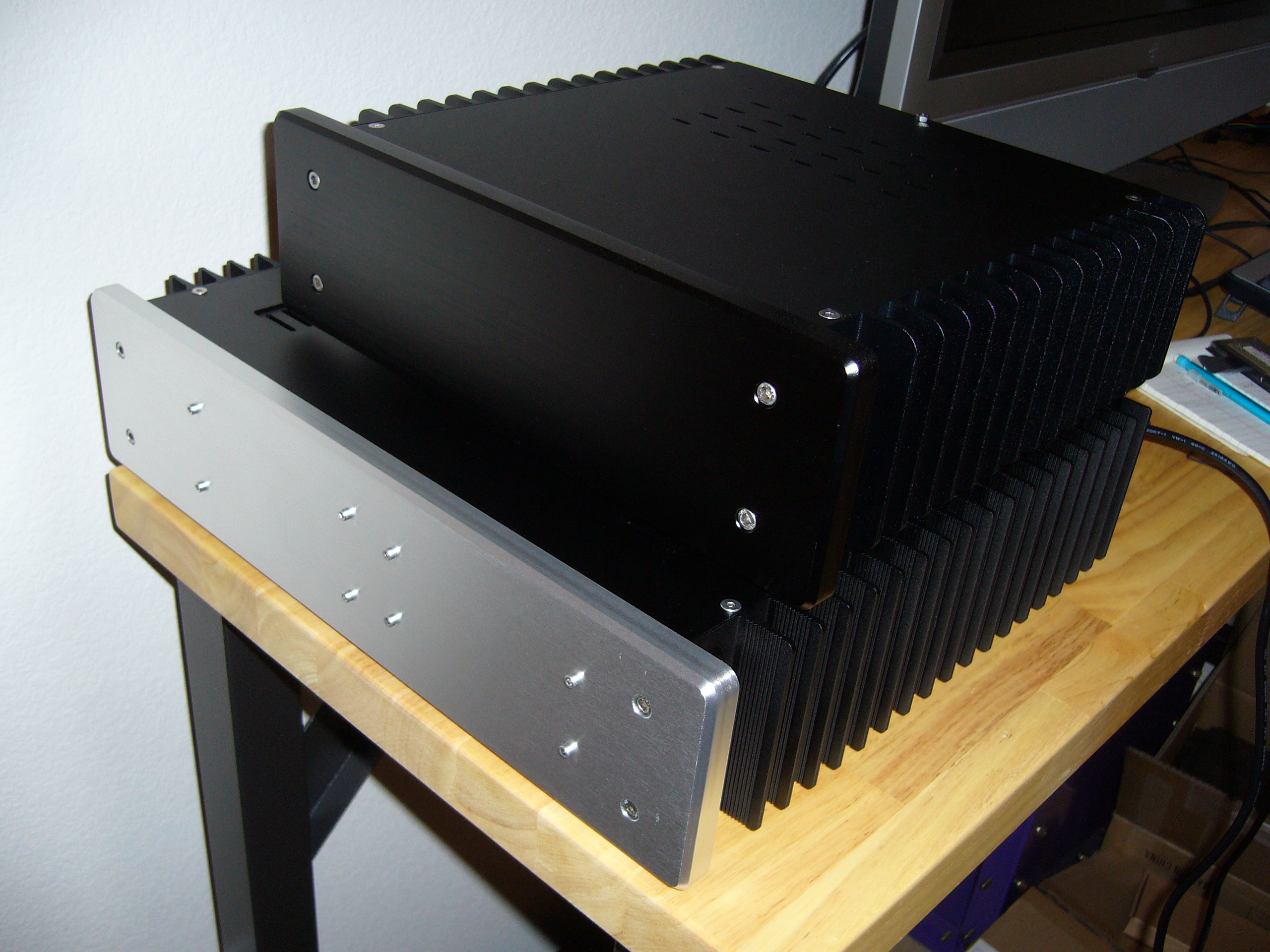 And here it is, sitting on the H5v3. Eventually it should become my firewall.