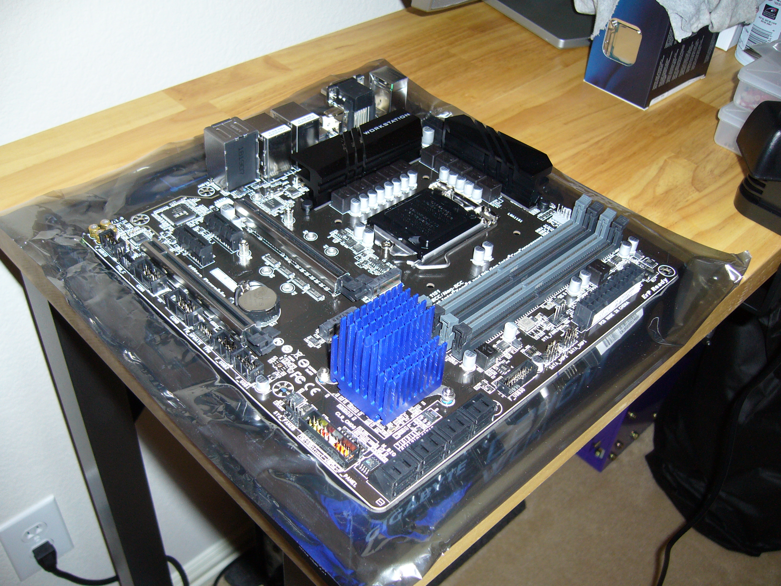
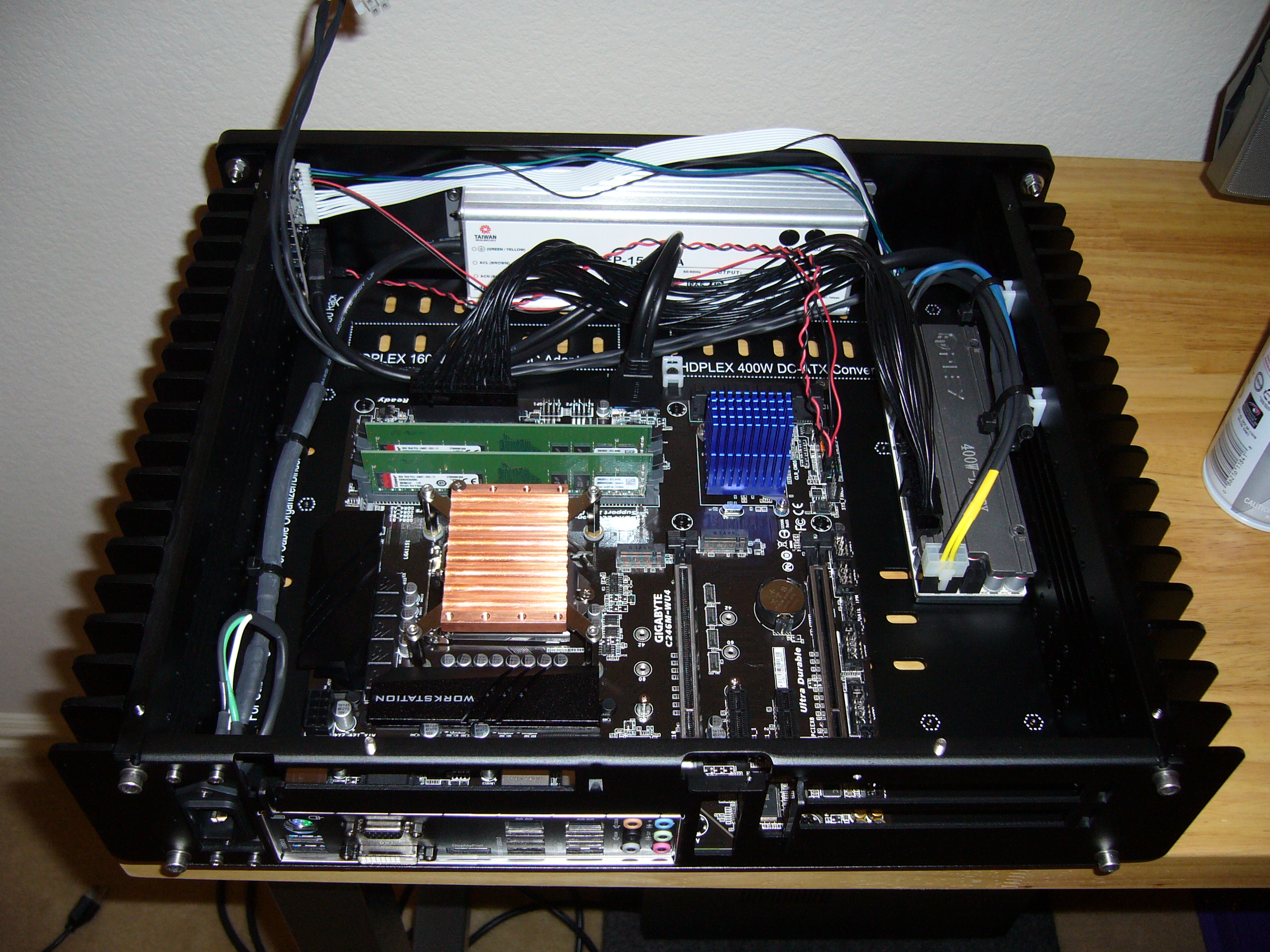
 Here is what I was working with. I chose a Micro ATX board because more expansion slots do not help me (particularly with the backplate available on
this model when I purchased it) and an ATX board would consume more space on the bottom plate. Rule of thumb: PC enclosures are a lot tighter than
they appear, so get something larger than you think you will need.
Here is what I was working with. I chose a Micro ATX board because more expansion slots do not help me (particularly with the backplate available on
this model when I purchased it) and an ATX board would consume more space on the bottom plate. Rule of thumb: PC enclosures are a lot tighter than
they appear, so get something larger than you think you will need.
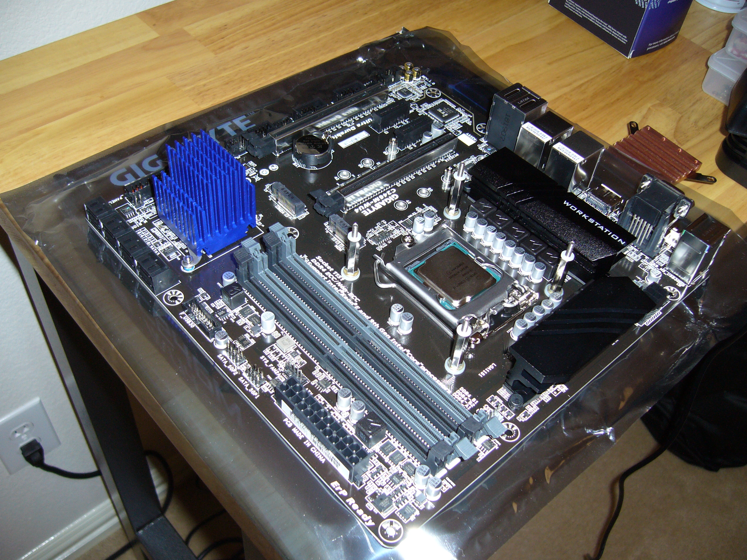
Of course, I replaced the chipset heat sink...
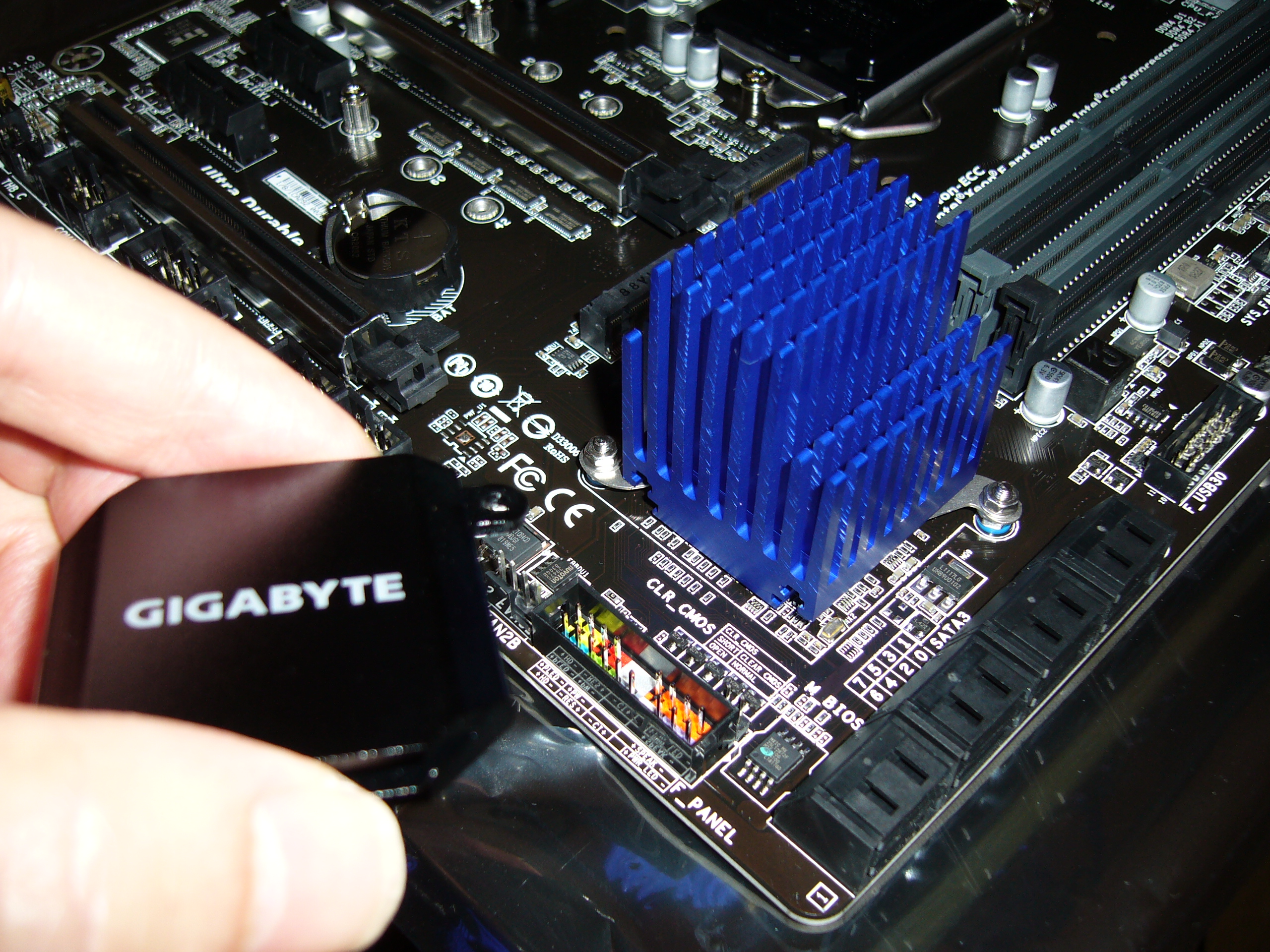 ...And this is why. The factory heat sink is effectively a small heat spreader, smooth and lightweight. The C246 is nominally a 6W chip; this one
runs nice and cool with the Zalman heat sink.
...And this is why. The factory heat sink is effectively a small heat spreader, smooth and lightweight. The C246 is nominally a 6W chip; this one
runs nice and cool with the Zalman heat sink.
Note the hard mount. No pushpins, no springs. I rely on the flexibility of the mounting tabs to provide pressure. I can usually find some combination of hardware from my collection to give me an appropriate mount.
 Here is at least the top side of my CPU block mounting setup. It is also a hard mount, which, while not ideal for a CPU, could be worse. Underneath
the motherboard I used the plastic backplate that came with the H5v2 kit, but I tapped the metal inserts through so I could drive screws through
them. The hexagonal threaded spacers are actually threaded all the way down onto these screws, which, not surprisingly, took a lot of screwing.
Here is at least the top side of my CPU block mounting setup. It is also a hard mount, which, while not ideal for a CPU, could be worse. Underneath
the motherboard I used the plastic backplate that came with the H5v2 kit, but I tapped the metal inserts through so I could drive screws through
them. The hexagonal threaded spacers are actually threaded all the way down onto these screws, which, not surprisingly, took a lot of screwing.
I placed the top set of nylon washers prior to cleaning the CPU cap, so naturally I sent them flying when I blew everything off with canned air. Just because they are a close fit and do not install easily does not mean they will not up and fly away, given half a chance.
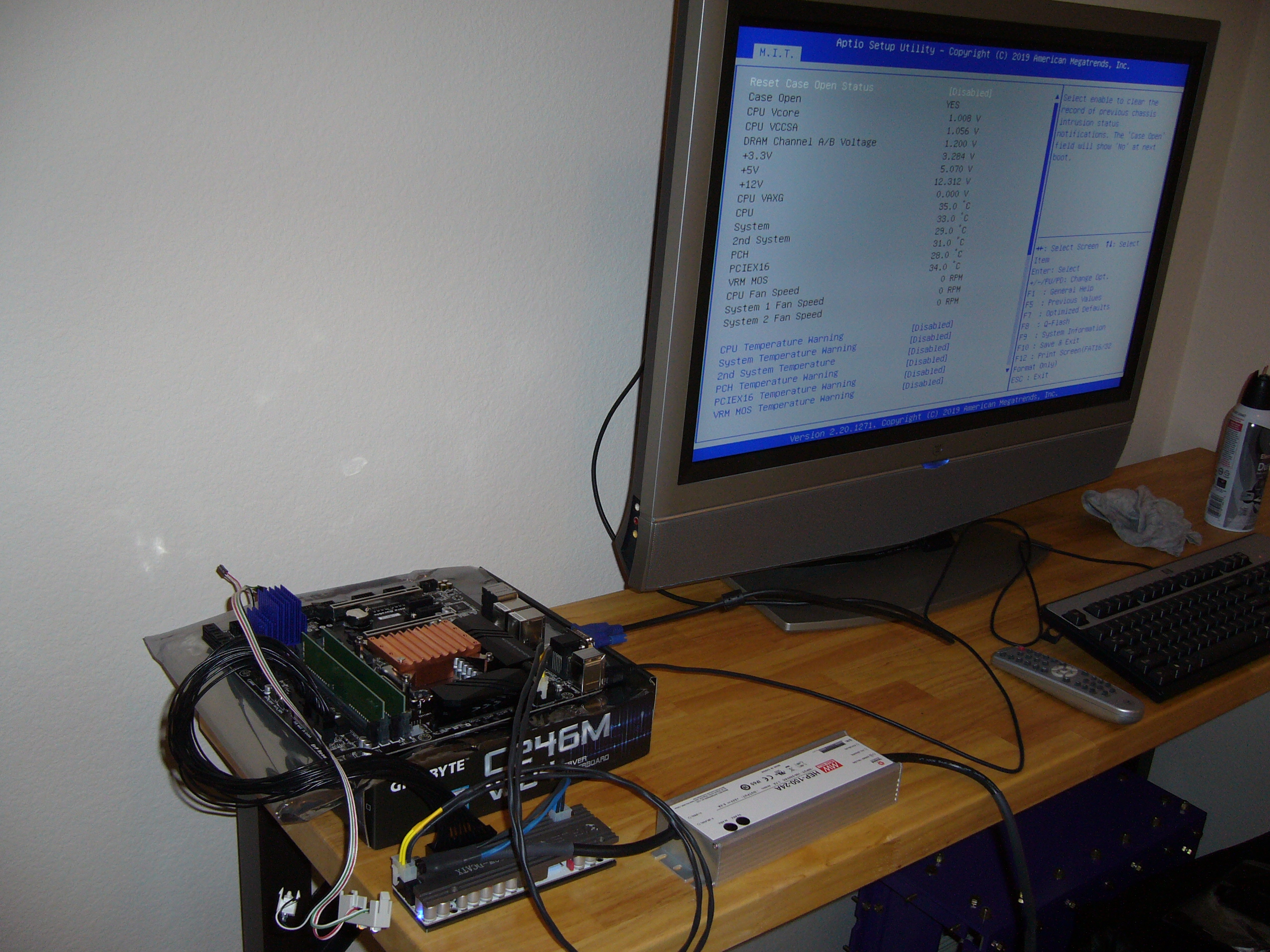 Testing the installation. You can run the system a fair amount of time before the copper CPU block heats up excessively.
You can see the power supply setup: a Meanwell HEP-150-24A AC-24VDC supply feeding into an HDPlex 400W DC-ATX converter. The Meanwell works very well (no pun intended), but it is pretty bloody big, and the fixed wiring is inconvenient (if expected on a fully encapsulated supply).
I may be bored enough to make most of my own cables, but I'm not entirely crazy, so I used the supplied 24-pin ATX cable.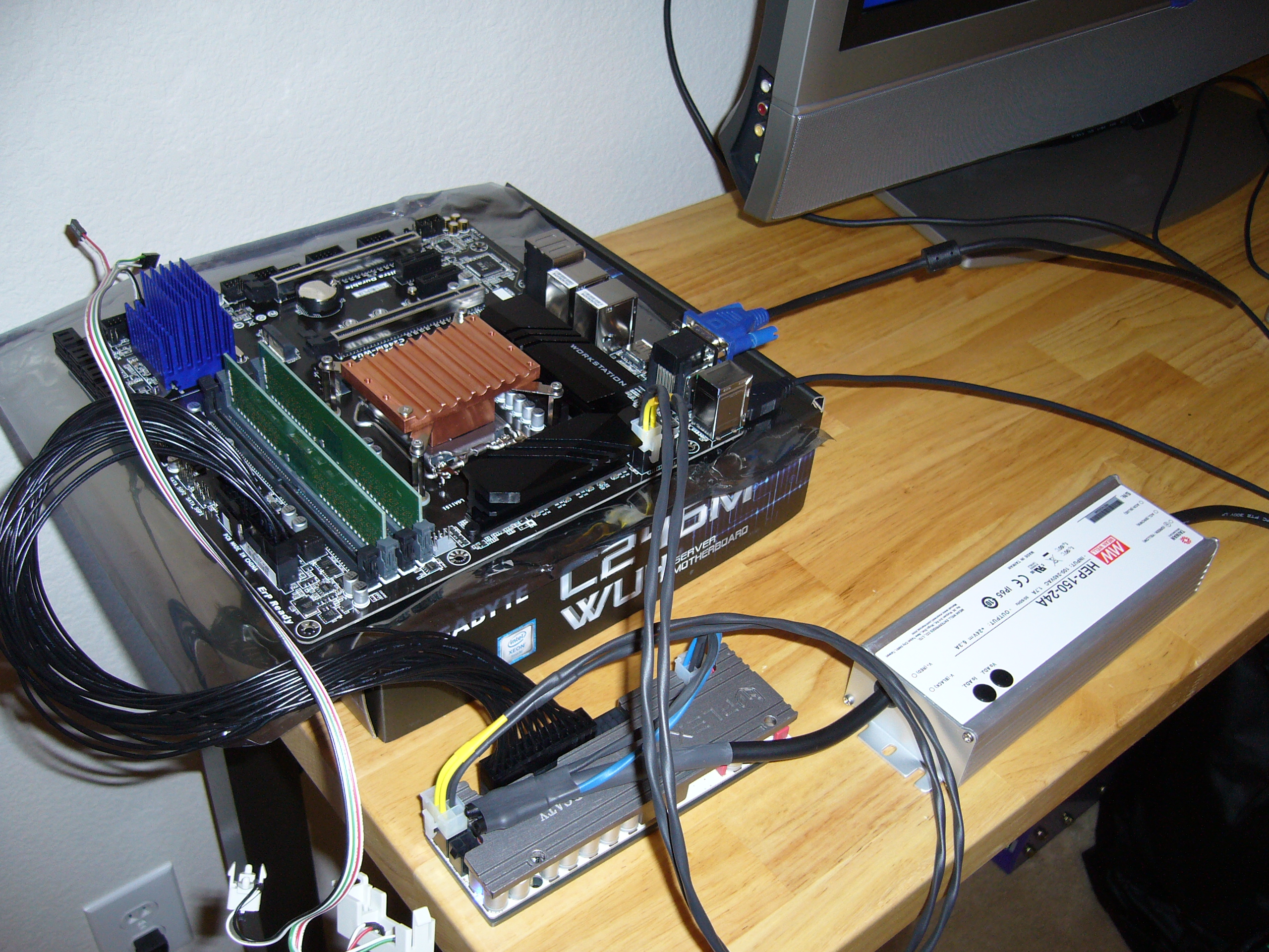 A closer view. For the life of me, I cannot recall why I stuck that screw into the CPU block. An orientation marker? The assembly should be
symmetric...
A closer view. For the life of me, I cannot recall why I stuck that screw into the CPU block. An orientation marker? The assembly should be
symmetric...
Yes, I stole the front panel wiring from an old case. Much handier than crossing power switch pins with a conductive tool, and I can hook up LEDs and a reset switch if I'm bored. Problem is, I keep misplacing the damn thing.
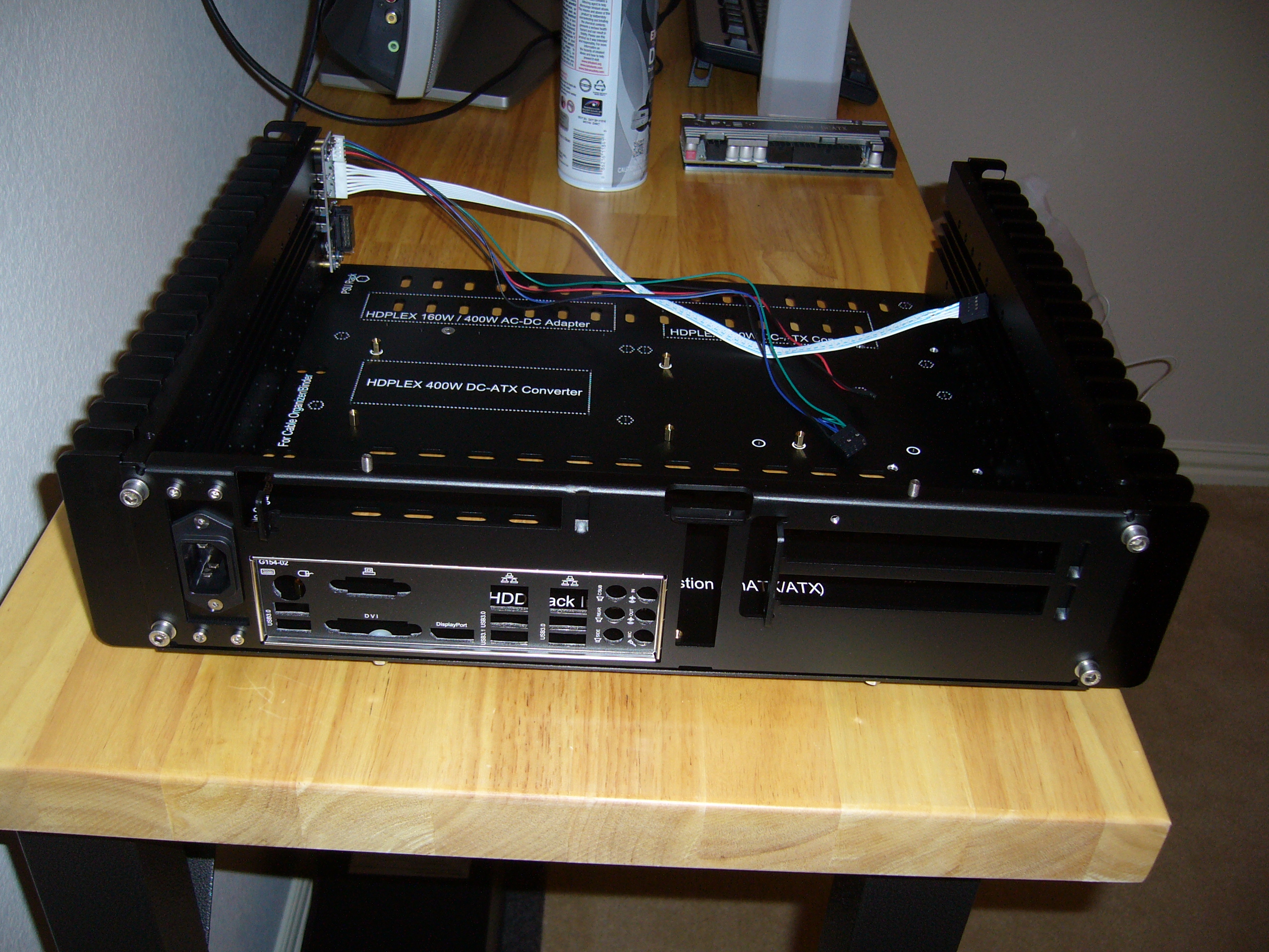
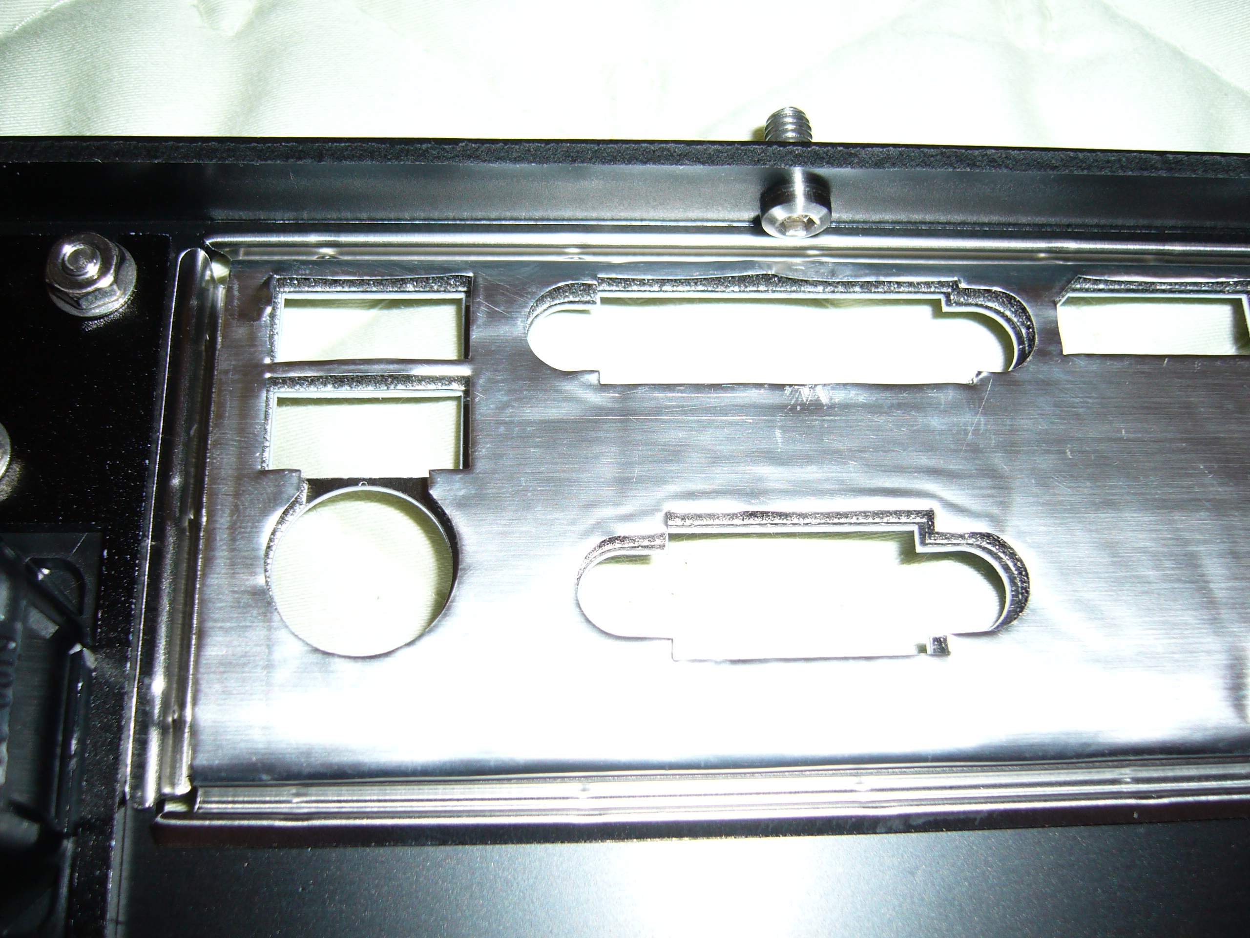 Close-up view of the backplate stud adjacent to the motherboard I/O panel. It is a button head screw that I chucked up in a drill press and used a
4.5" disc sander, a file, and sandpaper to reduce the head diameter. The flange on this model backplate was too shallow to fit much of anything next
to the I/O shield.
Close-up view of the backplate stud adjacent to the motherboard I/O panel. It is a button head screw that I chucked up in a drill press and used a
4.5" disc sander, a file, and sandpaper to reduce the head diameter. The flange on this model backplate was too shallow to fit much of anything next
to the I/O shield.
Note how close the power inlet flange is to the I/O shield as well. Tight. And this is HDPlex's large case.
 Here is a view of the screw above with its companion, a standard socket head capscrew which just barely fits onto the flange. All four of these
screws are Loctited , of course. Purple (low strength) Loctite is sufficient.
Here is a view of the screw above with its companion, a standard socket head capscrew which just barely fits onto the flange. All four of these
screws are Loctited , of course. Purple (low strength) Loctite is sufficient.
 Here is the trimmed screw with its insulator in place. I do not risk short circuits.
The insulator is a nylon spacer that I trimmed with a chisel. It is tough to cut one of these precisely, but a single whack with a sharp chisel makes easy work of it. The insulator fits tightly onto the screw head, and once trapped by the motherboard, is not going anywhere.
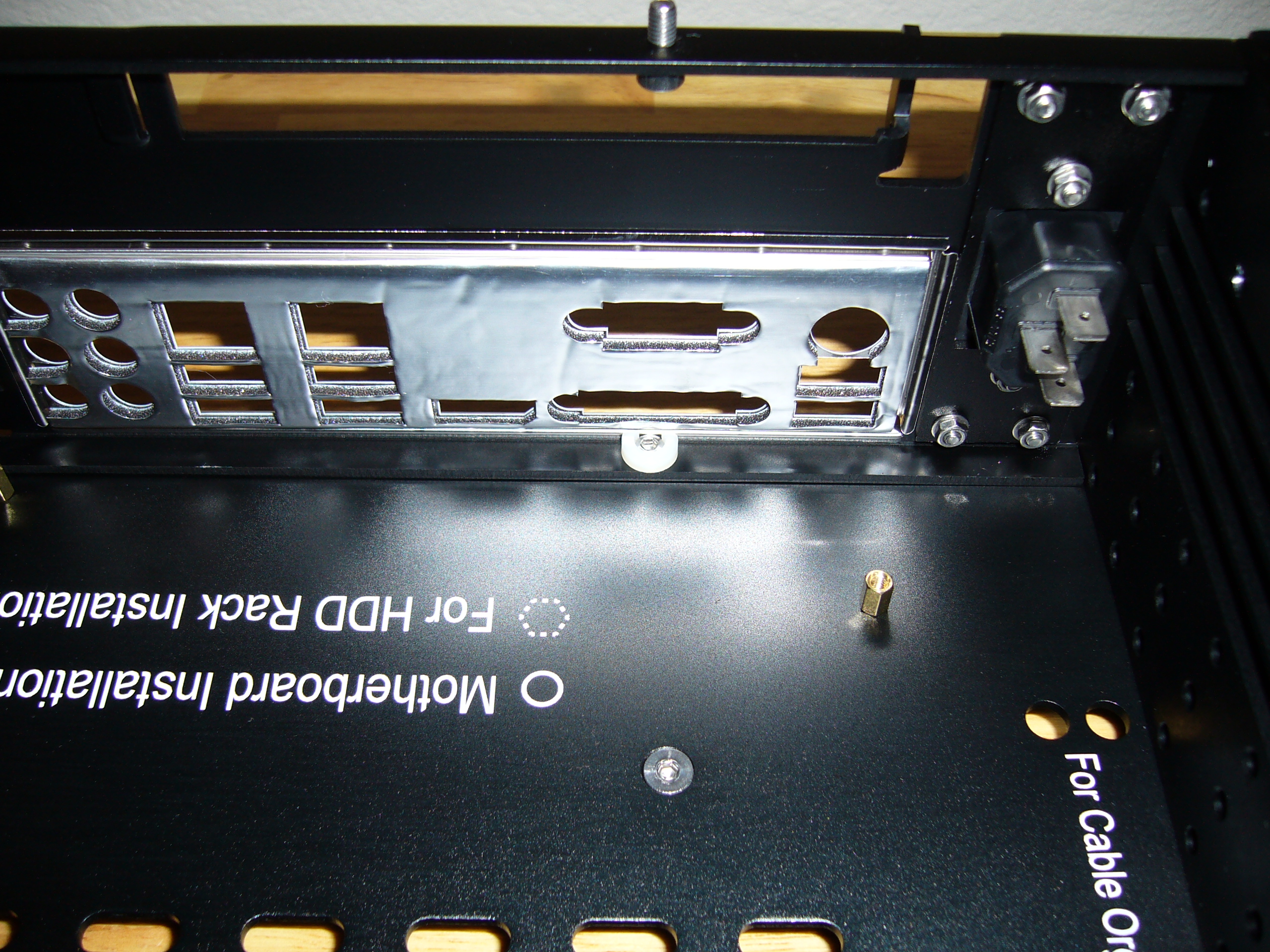
Damn, that power entry is right there... Get that mounted while you have the chance, or you will regret it later.
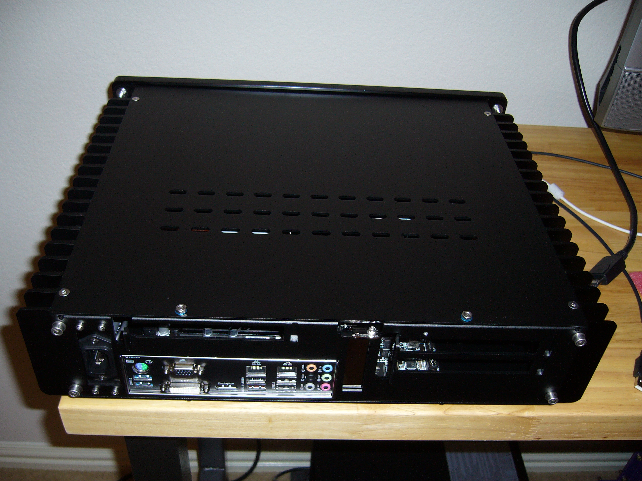
Also visible here is the head of one of the four feet screws (the stainless countersunk screw in the bottom plate), Loctited into place like the backplate studs. You do not want that coming loose underneath the motherboard.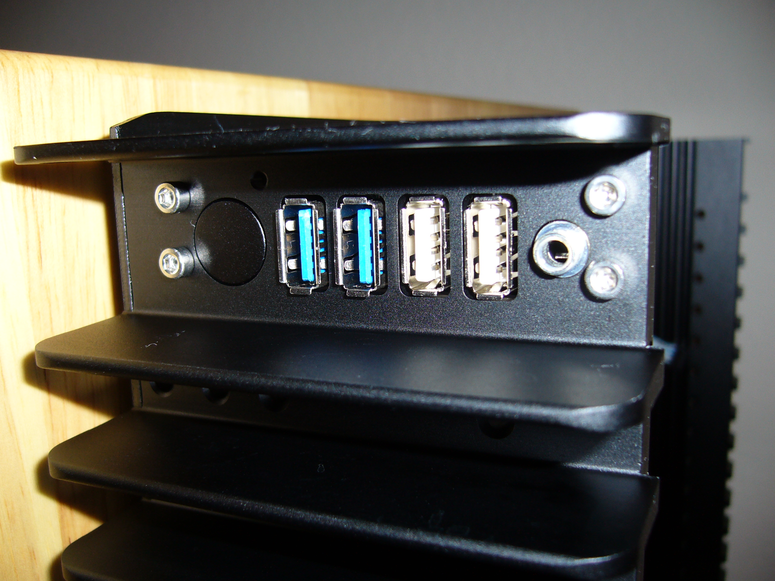 Close view of the enclosure I/O panel. As with much of the enclosure, I used my own hardware and methods.

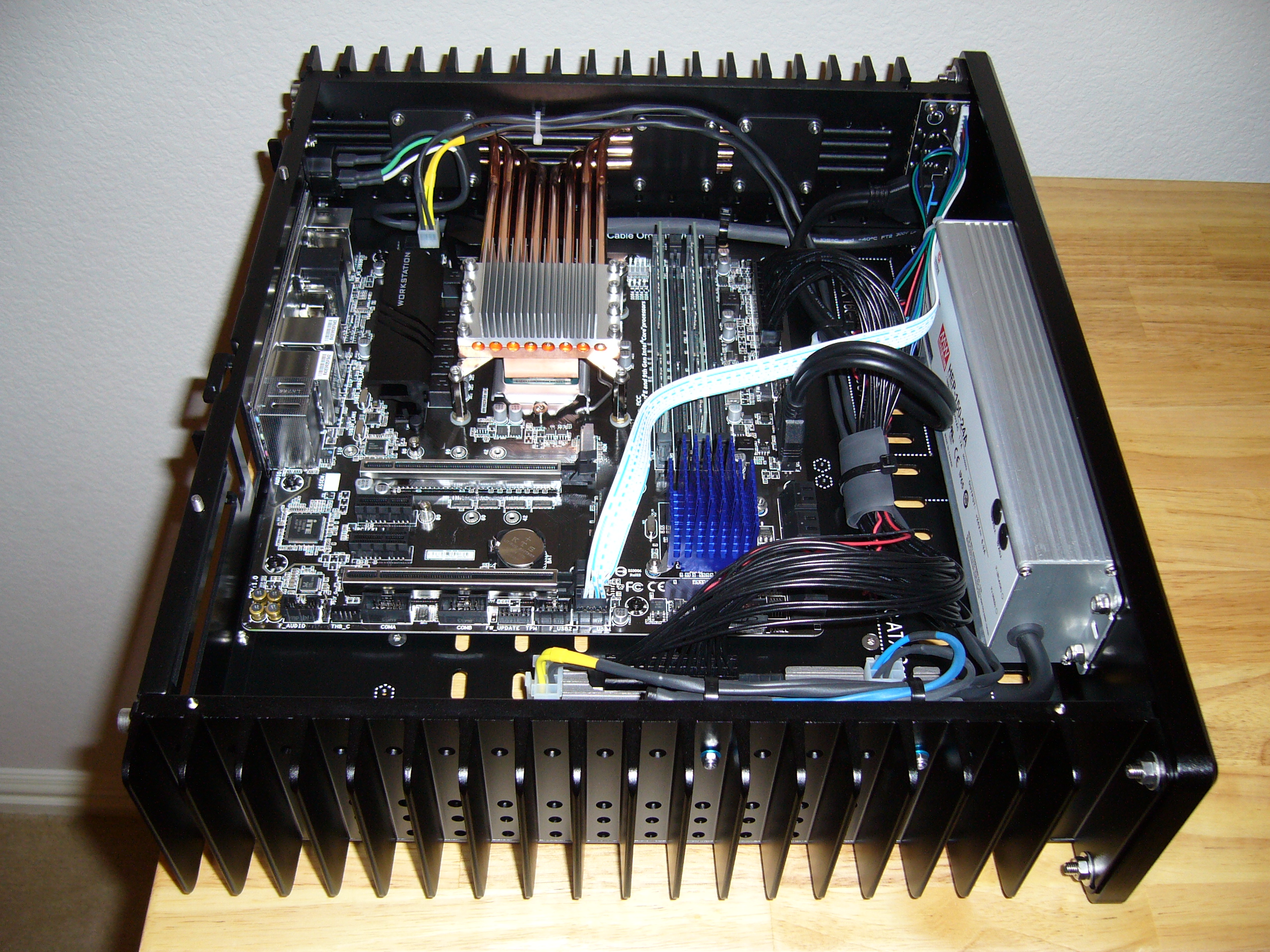
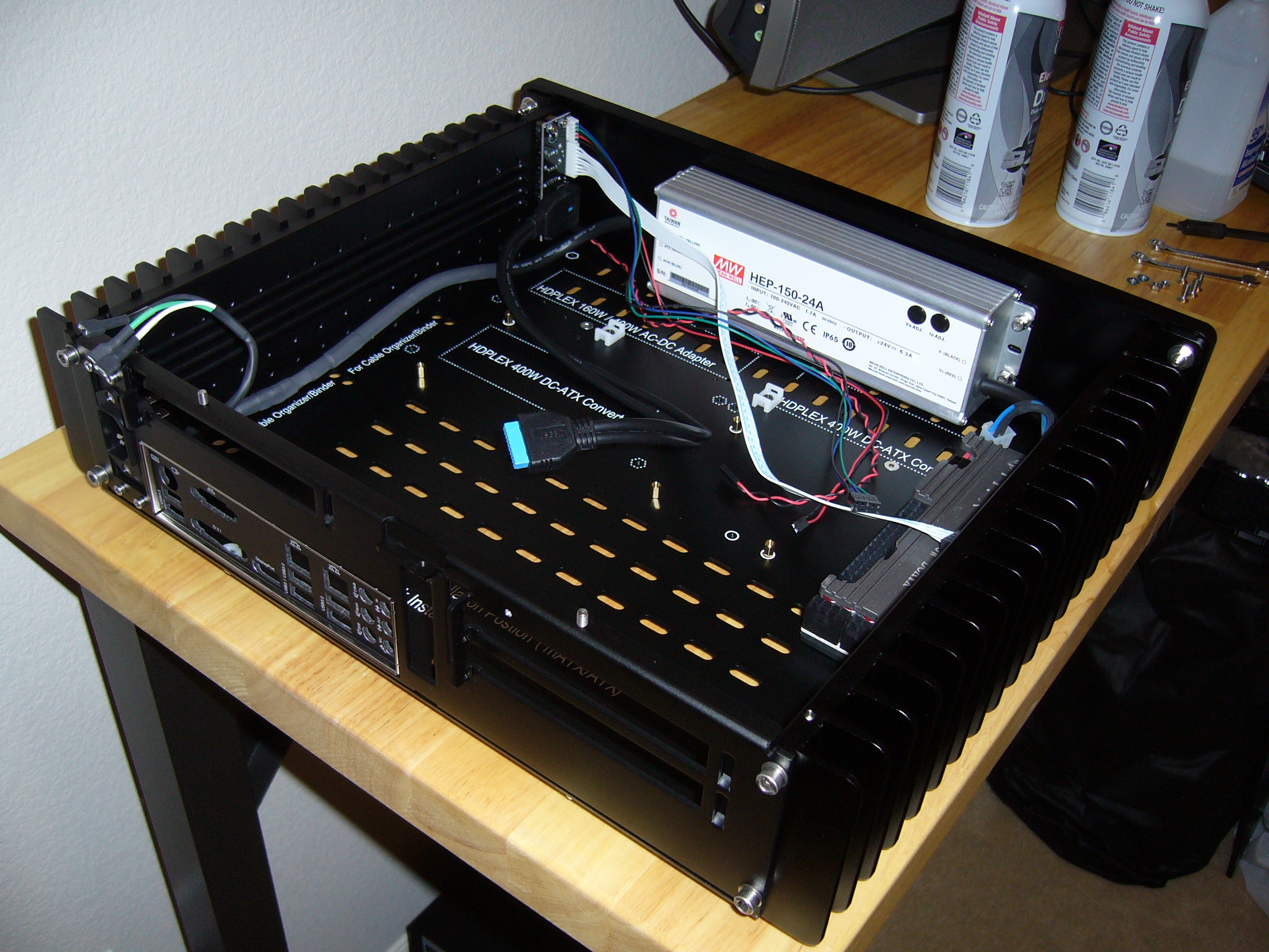 Now the power supplies are in place. Both are mounted over thermal pads.
I have sets of washers that I use specifically as spacers for thermal pads. I generally use .75mm or 1mm soft (~50 Shore 00) pads, with .5mm or .75mm washers respectively. While installing a screw with a small pile of washers (e.g. screw, washer, mounting surface, washer, mounting flange, washer, nut) is annoyingly fiddly, I end up with a nice solid mount with a specific, uniform compression of the thermal pad.
For the faceplate, I always use M5 set screws, Loctited into place, and nuts. Much less fiddly than trying to drive socket head screws in that tight spot.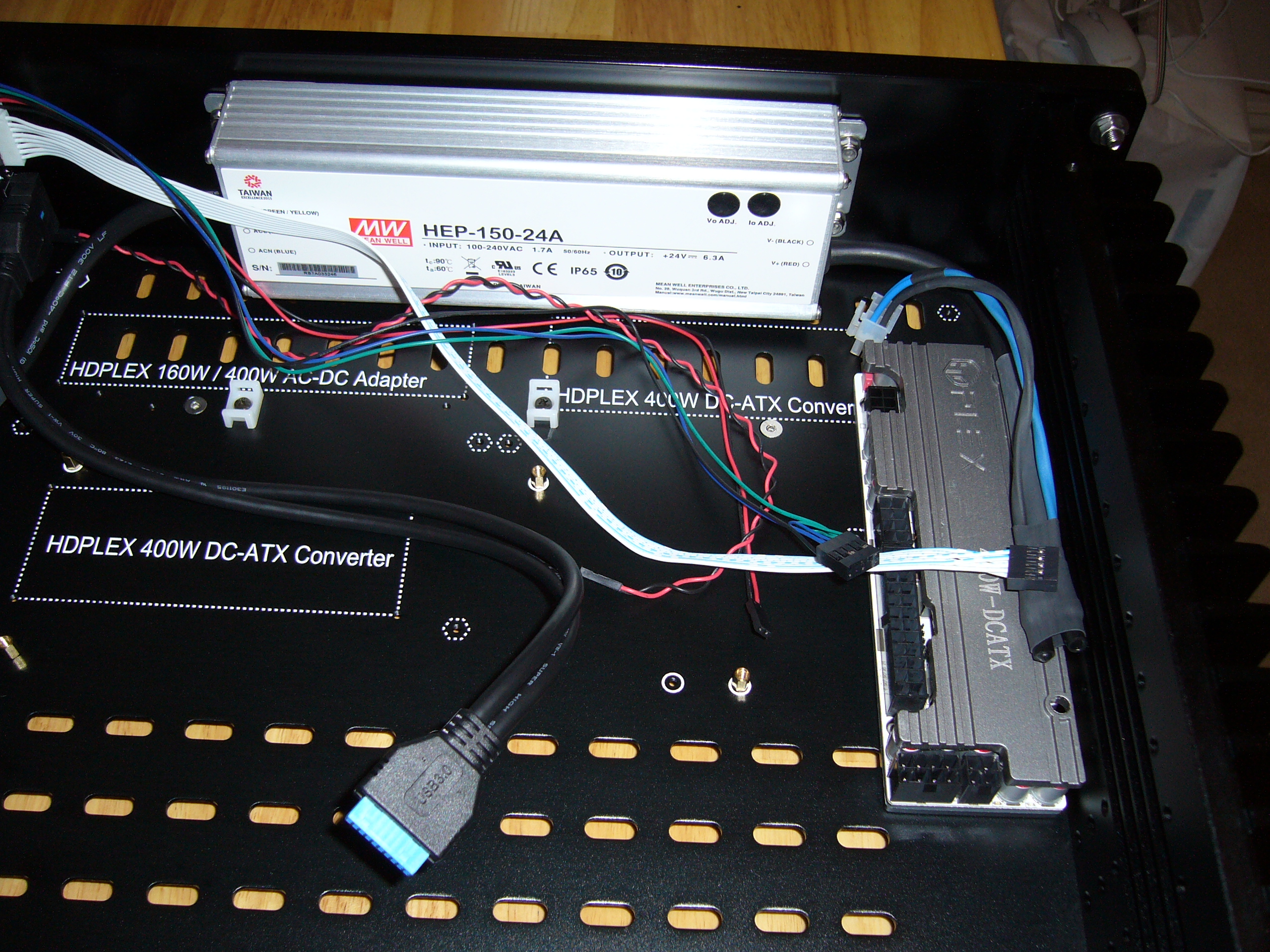 Note that when I built another of these (the H5v3), I used a smaller AC-DC supply and mounted both supplies to the faceplate, freeing up space on
the slot-side heat sink. These days, I suppose I would try HDPlex's GaN AC-ATX power supply, and save even more space.
Note that when I built another of these (the H5v3), I used a smaller AC-DC supply and mounted both supplies to the faceplate, freeing up space on
the slot-side heat sink. These days, I suppose I would try HDPlex's GaN AC-ATX power supply, and save even more space.

 Heat pipe layout on these is pretty easy. The heat sink grooves hold the heat pipes, and the thermal compound helps to stick everything into place.
I use Arctic Silver 5, as it is effective, yet easy to apply. I apply it in the grooves to within around 1/4" (6mm) from the edges of any exposure
around the heat pipes, determined by a dry layout. I also take notes, and stick blue painter's tape onto the heat sink and mark locations on it, as
thermal compound that does not make contact with a heat pipe is wasted and untidy, and cleaning it up is a pain in the ass. By design the stuff is
gooey, sticky, and loaded with very fine particulates. It gets everywhere if you are not careful.
Heat pipe layout on these is pretty easy. The heat sink grooves hold the heat pipes, and the thermal compound helps to stick everything into place.
I use Arctic Silver 5, as it is effective, yet easy to apply. I apply it in the grooves to within around 1/4" (6mm) from the edges of any exposure
around the heat pipes, determined by a dry layout. I also take notes, and stick blue painter's tape onto the heat sink and mark locations on it, as
thermal compound that does not make contact with a heat pipe is wasted and untidy, and cleaning it up is a pain in the ass. By design the stuff is
gooey, sticky, and loaded with very fine particulates. It gets everywhere if you are not careful.
I only (intentionally...) apply compound to the CPU block grooves (and not the CPU block cap) and the deepest 3mm of the heat sink grooves, as these are the only useful points of contact. I stand the enclosure on its side to goop the heat sink so I am working with gravity to confine the thermal compound.
Once you have applied the thermal compound and placed the heat pipes, capture them by loosely applying the CPU block retainer cap, then carefully apply the retainer plates on the heat sink. Heat pipe fit on these later model enclosures is somewhat looser than on the old H10, so clamping the heat pipes to crush them into the grooves should not be necessary. Once you are done with the swearing, stop and admire your work. Whip out some Q-Tips and isopropanol (get the good stuff - 99% - as it's more
effective and evaporates more quickly) and clean up any escaped thermal compound. My eyesight is not good, so I get my face down into the work and
try to cover all angles - you might be surprised where little strings of thermal compound can end up.
Once you are done with the swearing, stop and admire your work. Whip out some Q-Tips and isopropanol (get the good stuff - 99% - as it's more
effective and evaporates more quickly) and clean up any escaped thermal compound. My eyesight is not good, so I get my face down into the work and
try to cover all angles - you might be surprised where little strings of thermal compound can end up.
Then plug everything in and tie down the cables.

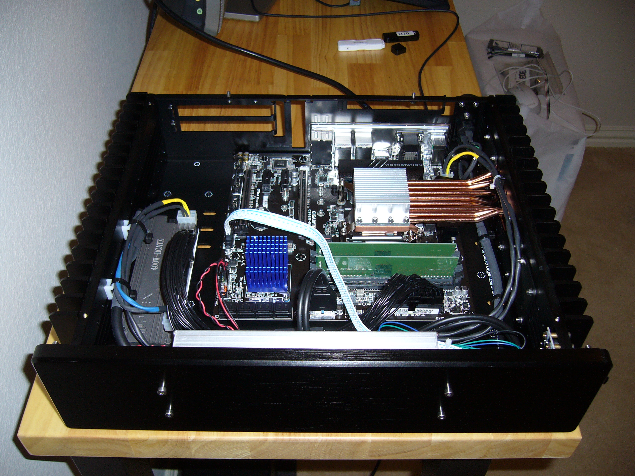
 In this view you can get a good view of the ATX power cable and how it is tied down. Insulation damage offends me, so I shrink some large tube and
slice it, then I apply it where I cannot conveniently apply the shrink tube directly (and sometimes where I can). I shrink the tube because it is
tougher and more flexible it its recovered state.
In this view you can get a good view of the ATX power cable and how it is tied down. Insulation damage offends me, so I shrink some large tube and
slice it, then I apply it where I cannot conveniently apply the shrink tube directly (and sometimes where I can). I shrink the tube because it is
tougher and more flexible it its recovered state.
You may notice that I double-insulate (at least) every cable that I make these days. I am that paranoid.

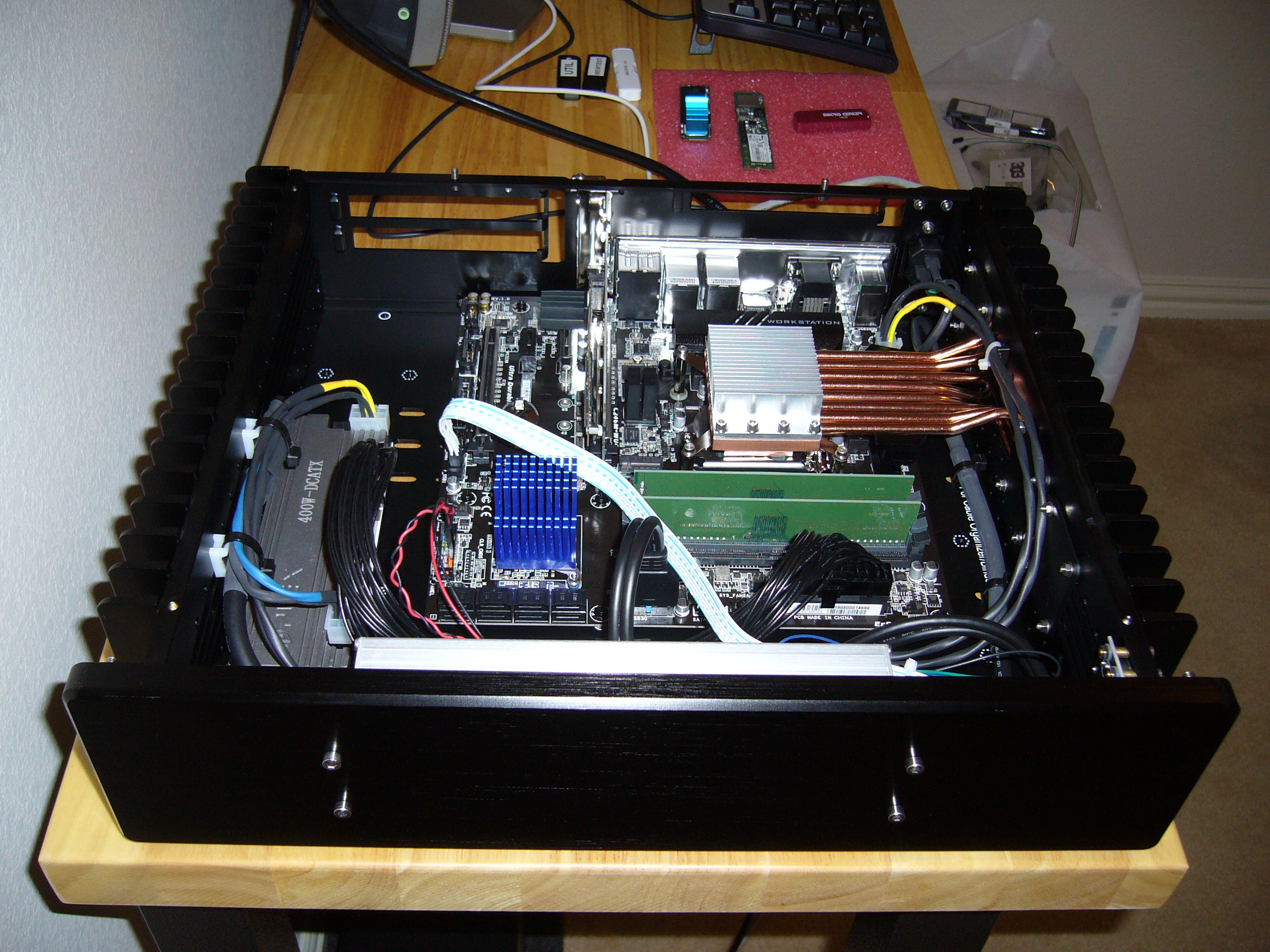 They are a bit tough to make out in this photo, but if you look closely you can see the two M.2 SSDs installed, one on a carrier card in the x16
slot and the other in the M.2 slot next to it.
They are a bit tough to make out in this photo, but if you look closely you can see the two M.2 SSDs installed, one on a carrier card in the x16
slot and the other in the M.2 slot next to it.
Yeah , this did not work.
 I had considered thermals, but, silly me, I had not considered how bad it could be. Simply put, the M.2 form factor is complete crap for SSDs
(or anything else with similar power consumption). Hell, it's pretty much crap, period.
I had considered thermals, but, silly me, I had not considered how bad it could be. Simply put, the M.2 form factor is complete crap for SSDs
(or anything else with similar power consumption). Hell, it's pretty much crap, period.
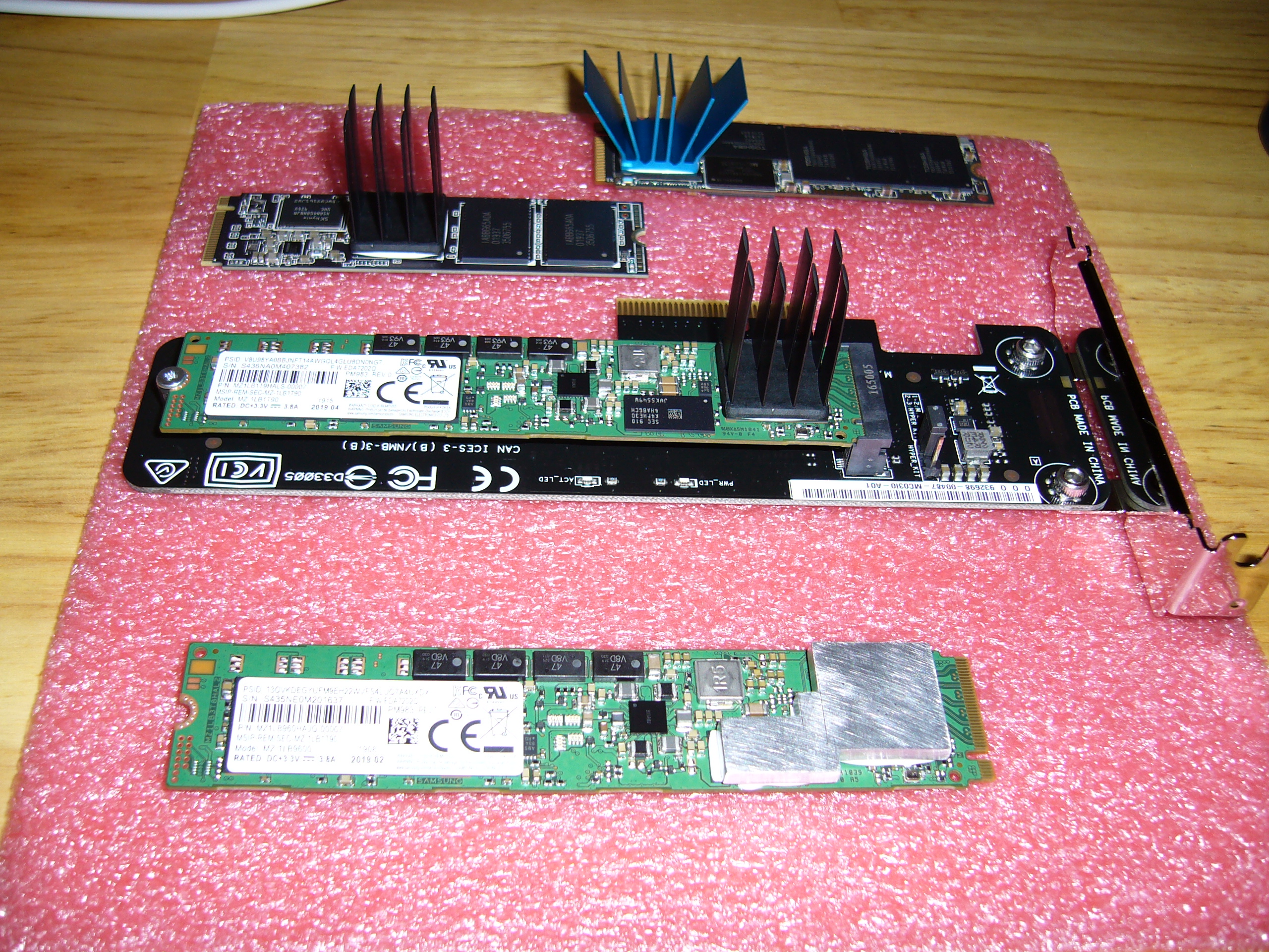
What I initially tried were the 17mm square x 25mm heat sinks on the controllers. Both SSDs throttled under write loads. So I scrounged another and added a spacer to it...
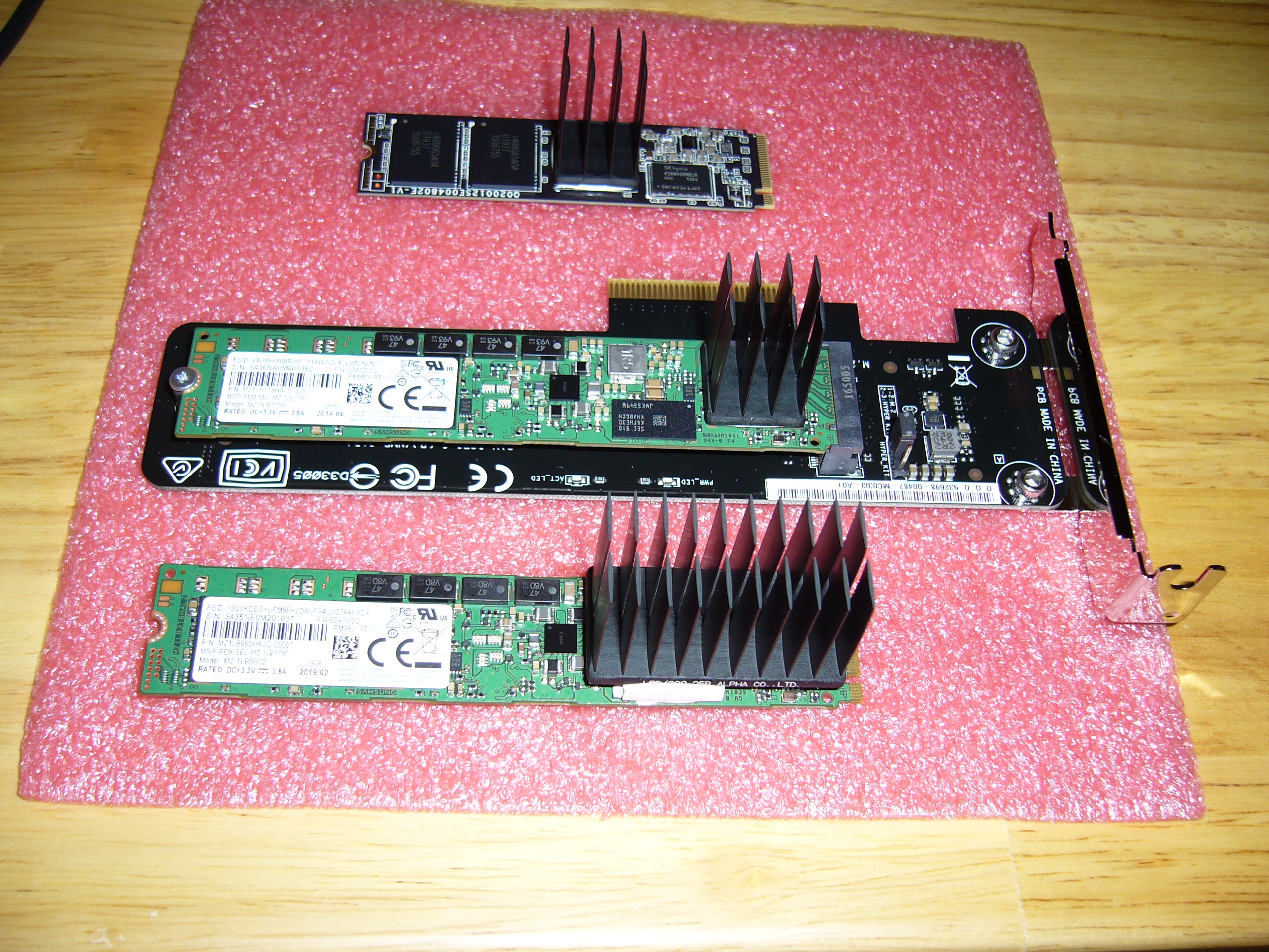 ...And a 40 x 20 x 25mm (LWH) heat sink to that. It is barely adequate.
These days, if you must use an M.2 SSD, look at Thermalright's HR-09 2280. Note that when installing an overall thermal pad on a paper-thin, flexible circuit board with a non-uniform component height, making certain of proper contact is... a challenge. M.2 circuit boards can flex in very non-intuitive ways when under pressure. In my later builds I use 2.5" SSDs. No more M.2.
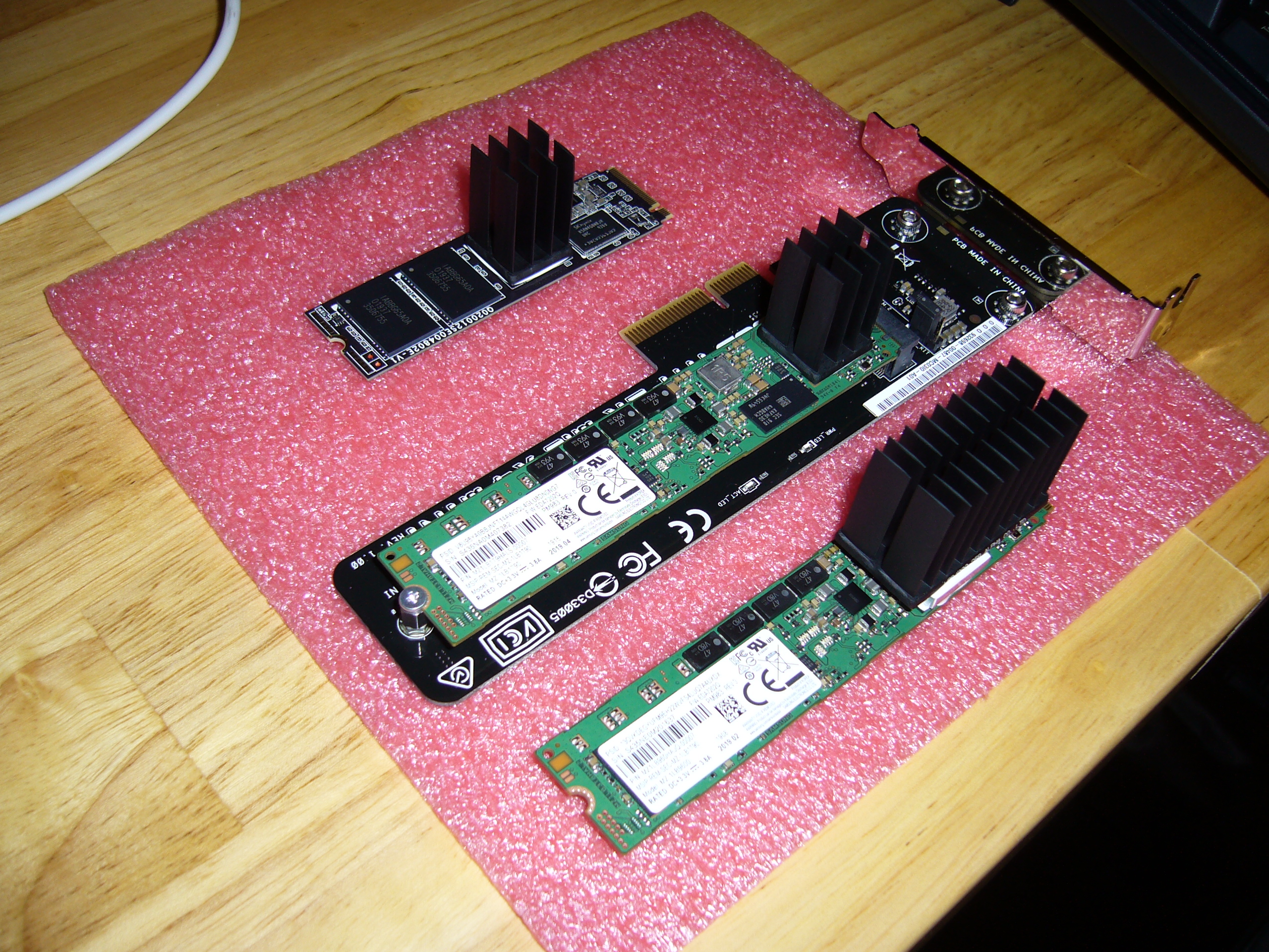
 Here is the final SSD installation: the M.2 with the larger heat sink... and a Samsung 983 ZET. The ZET uses the same controller as the M.2 SSD, a
PM983/983 DCT, and in the HHHL form factor with a decent heat sink works beautifully. Much cooler than the poor M.2. Note that most HHHL SSDs are
25W devices and would not work well in this application. The 983 ZET is an outlier, a 10W PCI-e x4 device.
Here is the final SSD installation: the M.2 with the larger heat sink... and a Samsung 983 ZET. The ZET uses the same controller as the M.2 SSD, a
PM983/983 DCT, and in the HHHL form factor with a decent heat sink works beautifully. Much cooler than the poor M.2. Note that most HHHL SSDs are
25W devices and would not work well in this application. The 983 ZET is an outlier, a 10W PCI-e x4 device.
By the way, the two SSDs are mirrored with Btrfs.
Side note on expansion card installation: The backplate on the H5v2 and H3v3 enclosures is designed such that it is normally removed when installing or removing expansion cards. My modified backplate mounting prevents this, so to install a card I had to loosen the backplate, remove the bracket from the card, insert it into the backplate, install the card, and fiddle the bracket onto the card while fiddling the backplate back into place. Most folks will want to simply follow the instructions and use the supplied hardware.
Side note on half-height mounting brackets: Most have projections stamped into the top mounting surface. These serve no useful purpose and interfere with secure installation. I tape them up and (carefully) hammer the surface flat for a better fit.
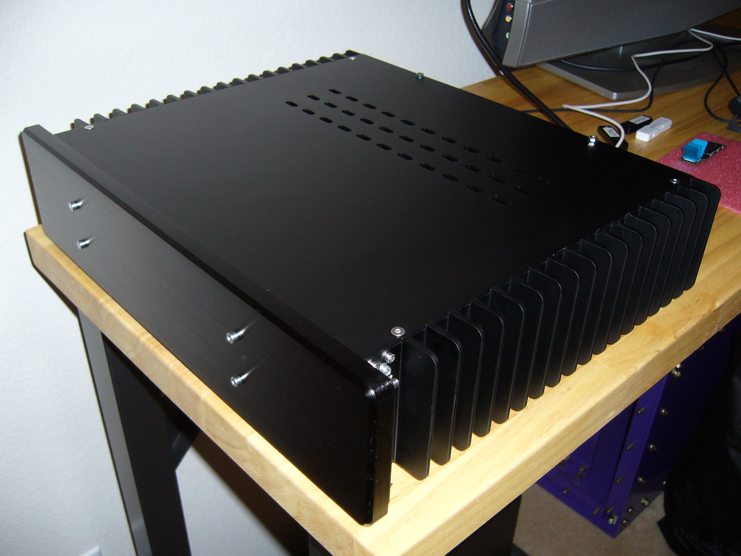 Complete. In a 30C/86F room it runs in the mid-60s. The hot spot is the M.2 SSD, which reaches 80C during an extended write benchmark (but does
not throttle).
Complete. In a 30C/86F room it runs in the mid-60s. The hot spot is the M.2 SSD, which reaches 80C during an extended write benchmark (but does
not throttle).
This machine now has 32GB of RAM (four sticks) and should eventually replace the H10.
2024 update: I stole the 983 ZET from this machine and installed it in the H5v3, so that one is now replacing the H10. Along with Ares6, the H3v3 and/or In Win 301 as firewalls, I now have a heat problem. (Again. Ares4 was also a cooker in a small room.)