 I do not seem to have taken any overall photos of the bare motherboard. Go figure.
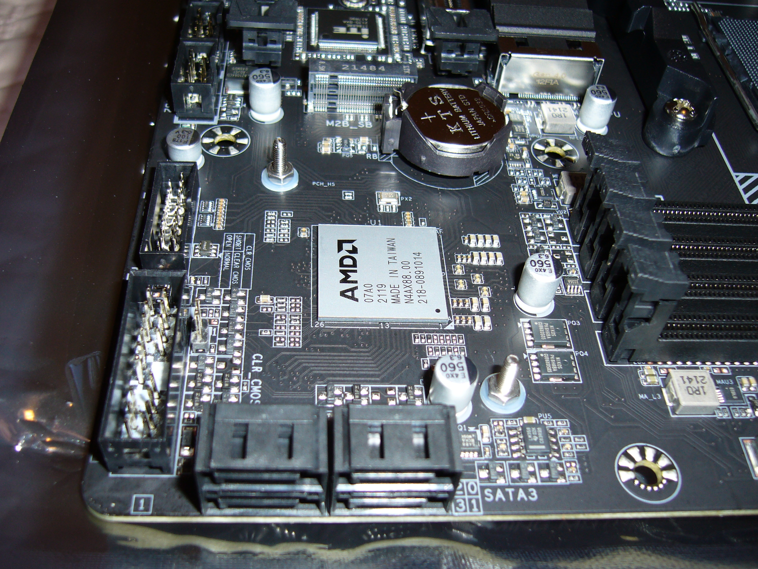
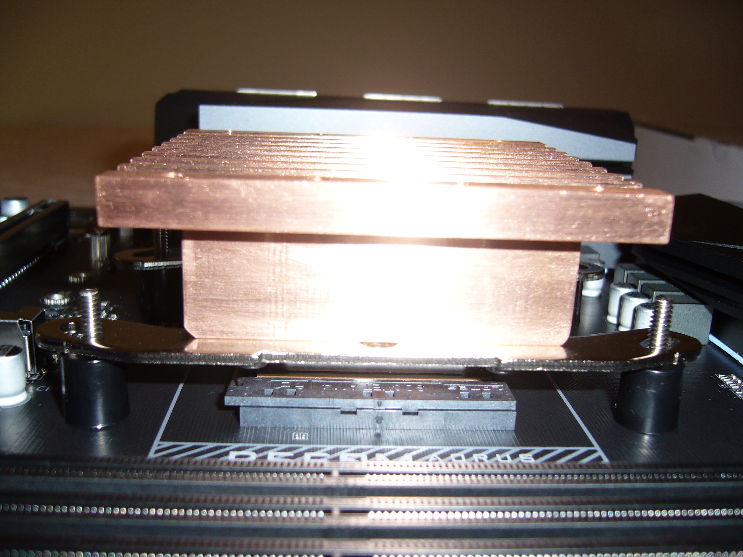
Here is a close up view of the B550 chip, with mounting points for the Zalman heat sink installed.
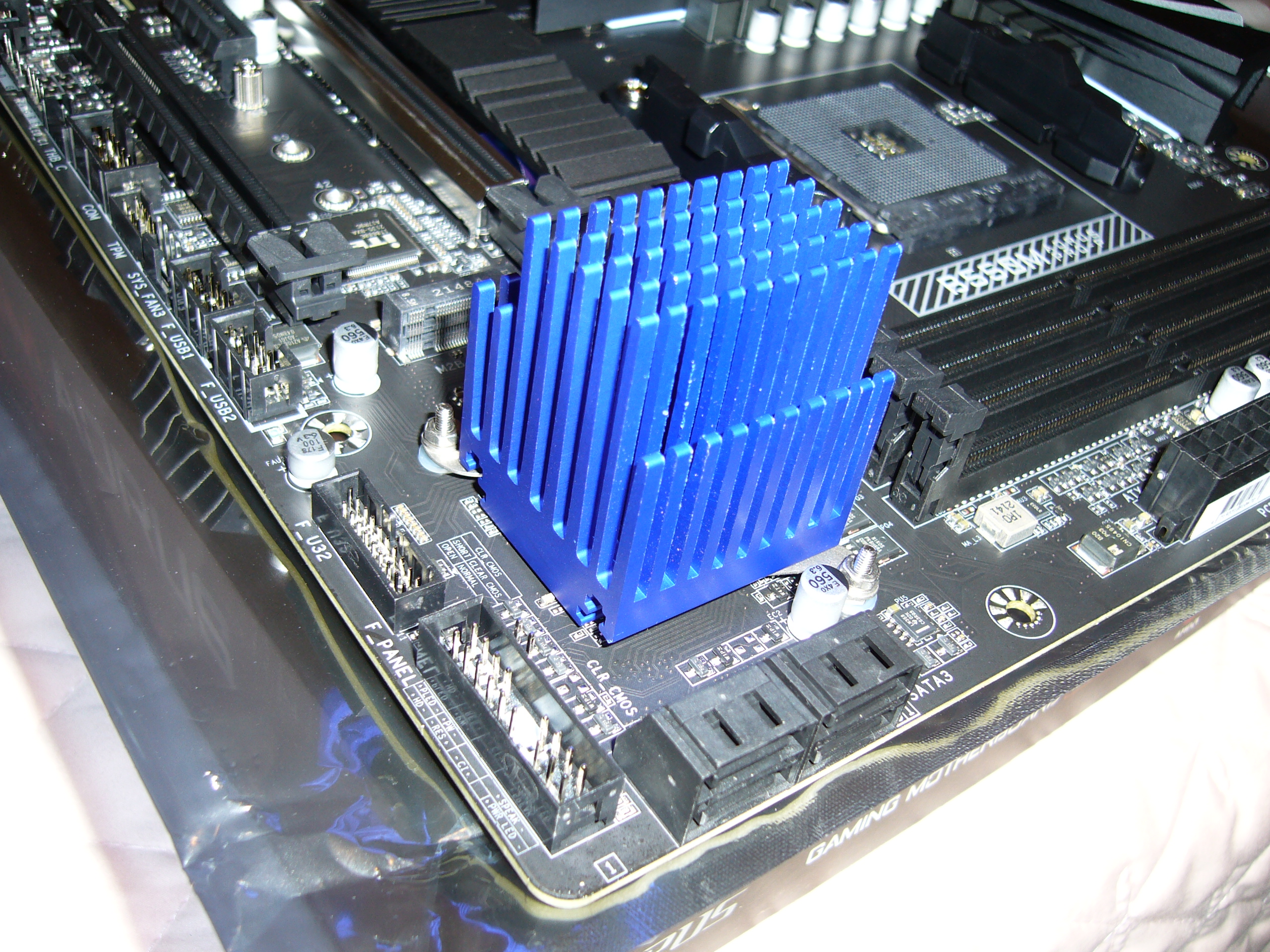 And with the heat sink installed on the chipset.
This motherboard has essentially the same layout as the C246M-WU4 in the H5v2. I chose this board in part because of the chipset location and heat sink mounting. In fact, the factory chipset heat sink on these two boards is identical aside from the markings. The equivalent Asus board, for instance, has the chipset mounted much closer to the slots, which would block a standard HHHL card in my installation.
While the B550 looks much the same as the 3 and 4 series chipsets, it runs much cooler.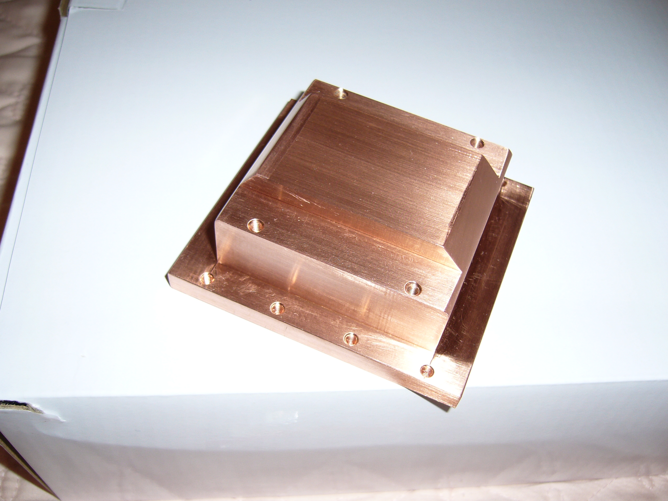 I could have left the "ears" on the CPU block (it would have fit)... but I couldn't.
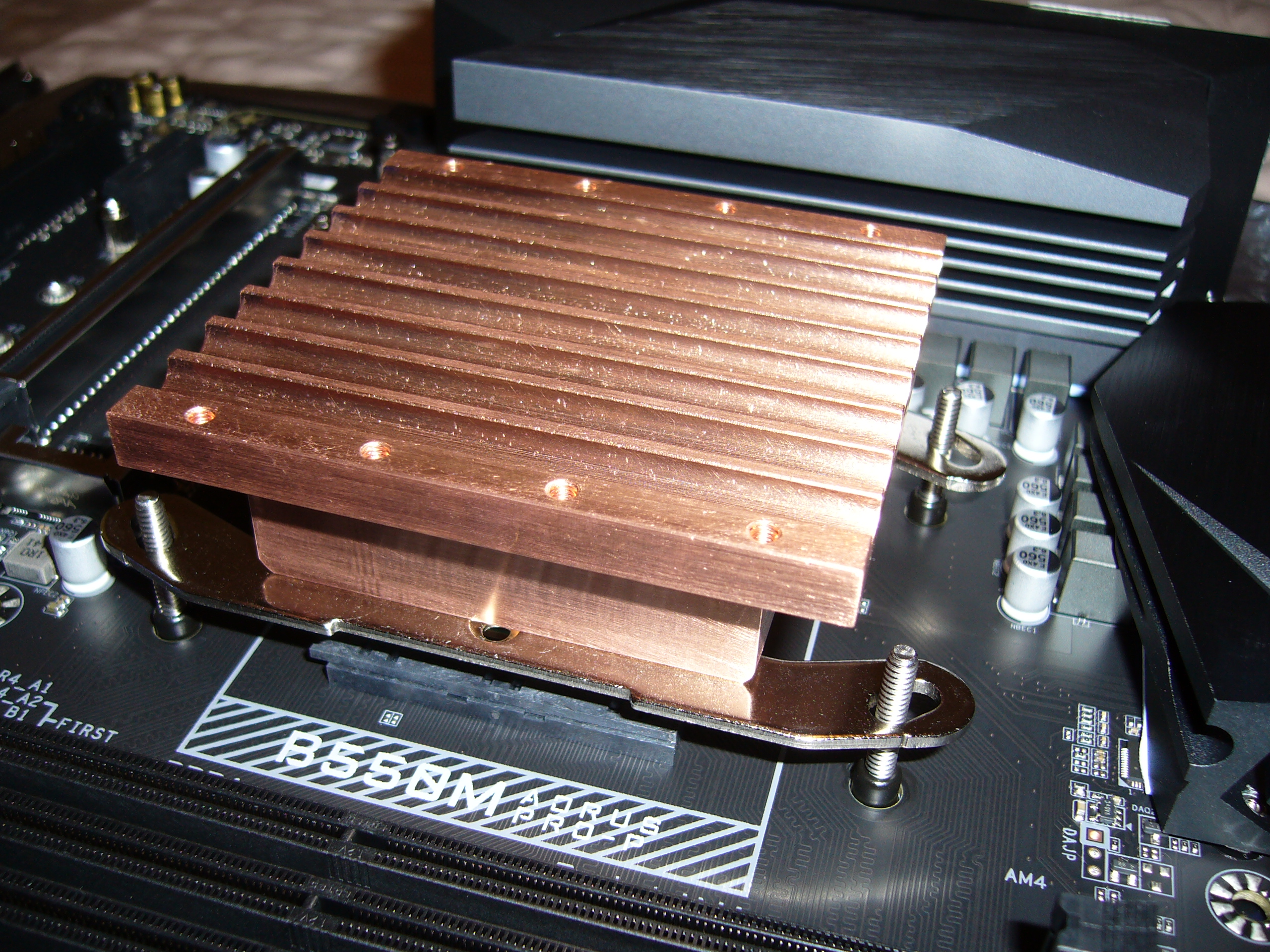
 Here it is with the mounting brackets installed. Yes, the brackets would fit the CPU block if I flipped them, but they would then not fit on the
backplate studs (without modification). This may not be pretty, but it works fine.
Here it is with the mounting brackets installed. Yes, the brackets would fit the CPU block if I flipped them, but they would then not fit on the
backplate studs (without modification). This may not be pretty, but it works fine.
 Yep, it fits... Note the alignment sleeves projecting through the board from the backplate. I used the backplate included with the motherboard, as
it was superior to the one included with the H5v3 kit. I just ran some screws up through it, Loctited, of course.
Yep, it fits... Note the alignment sleeves projecting through the board from the backplate. I used the backplate included with the motherboard, as
it was superior to the one included with the H5v3 kit. I just ran some screws up through it, Loctited, of course.
 Close view of the CPU block with the spacers in place. These spacers would not fit over the backplate sleeves noted above... without modification.
I simply counterbored them with a step bit (much easier to deal with than a grabby twist drill), by hand, as the spacers are quite soft.
Close view of the CPU block with the spacers in place. These spacers would not fit over the backplate sleeves noted above... without modification.
I simply counterbored them with a step bit (much easier to deal with than a grabby twist drill), by hand, as the spacers are quite soft.
One thing you cannot see in these photos is that the CPU block base is narrower than the AMD heat spreader, which is annoyingly unecessary given the gigantic size of the CPU block.
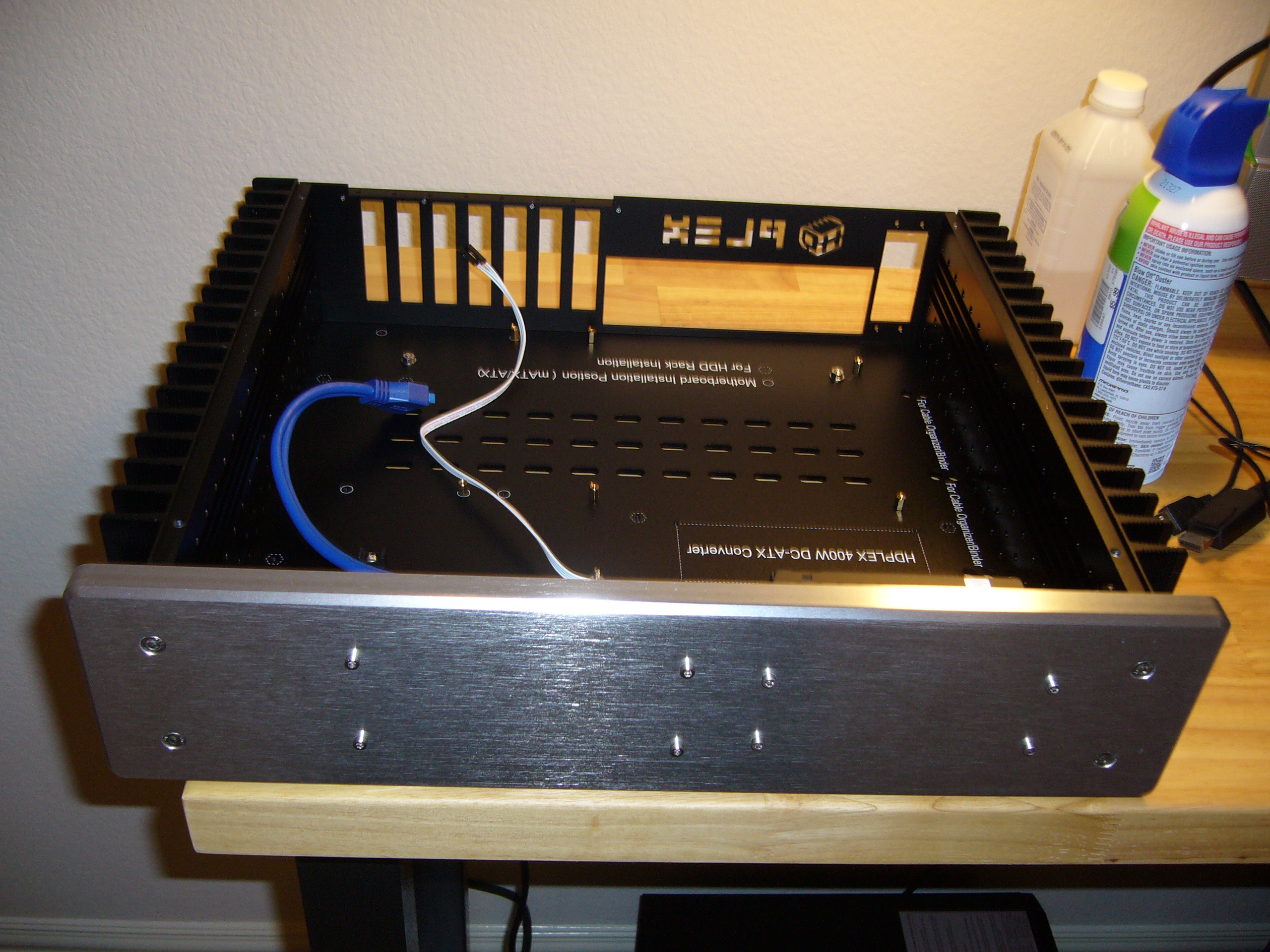
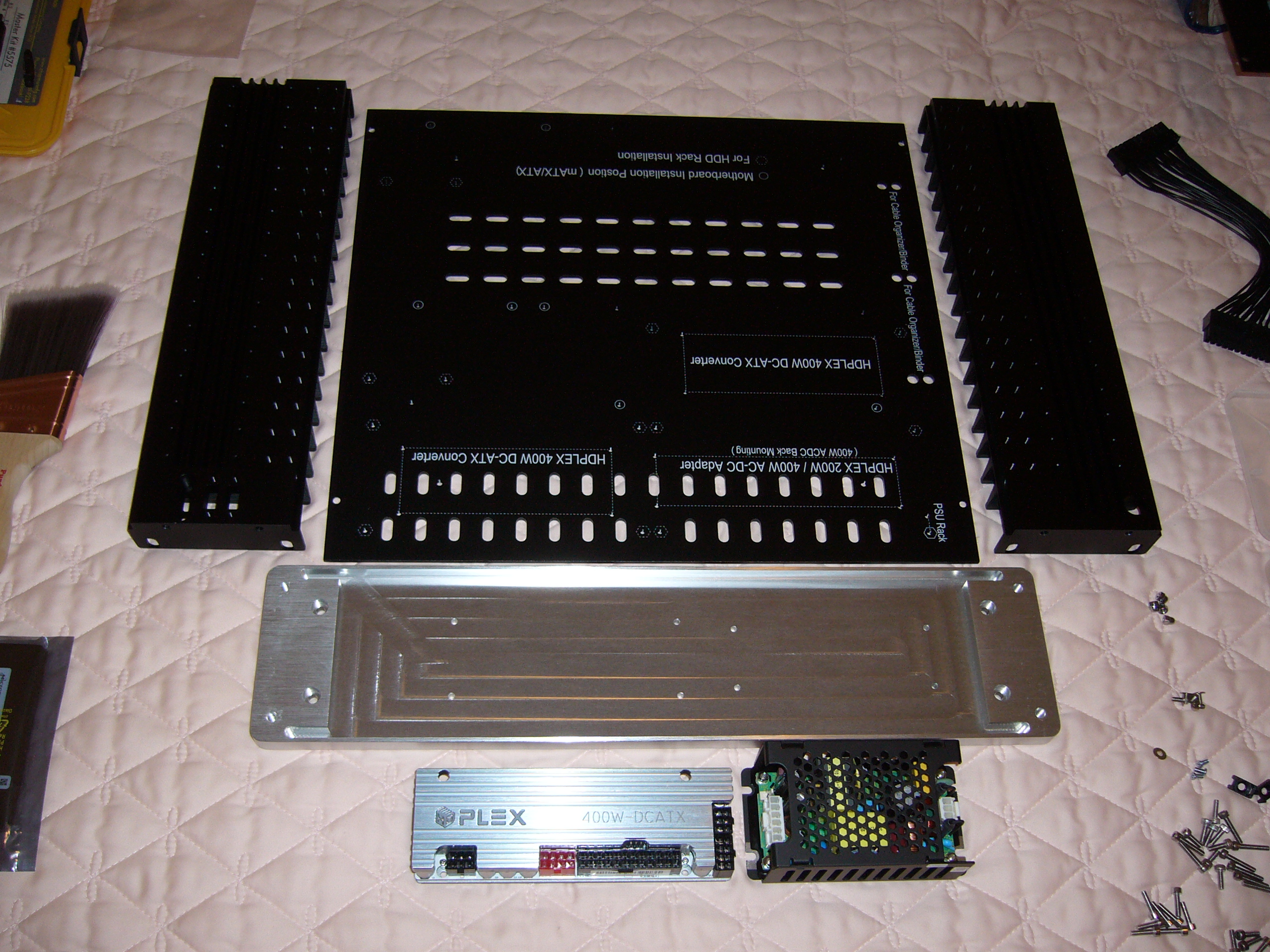 Component layout sanity check...
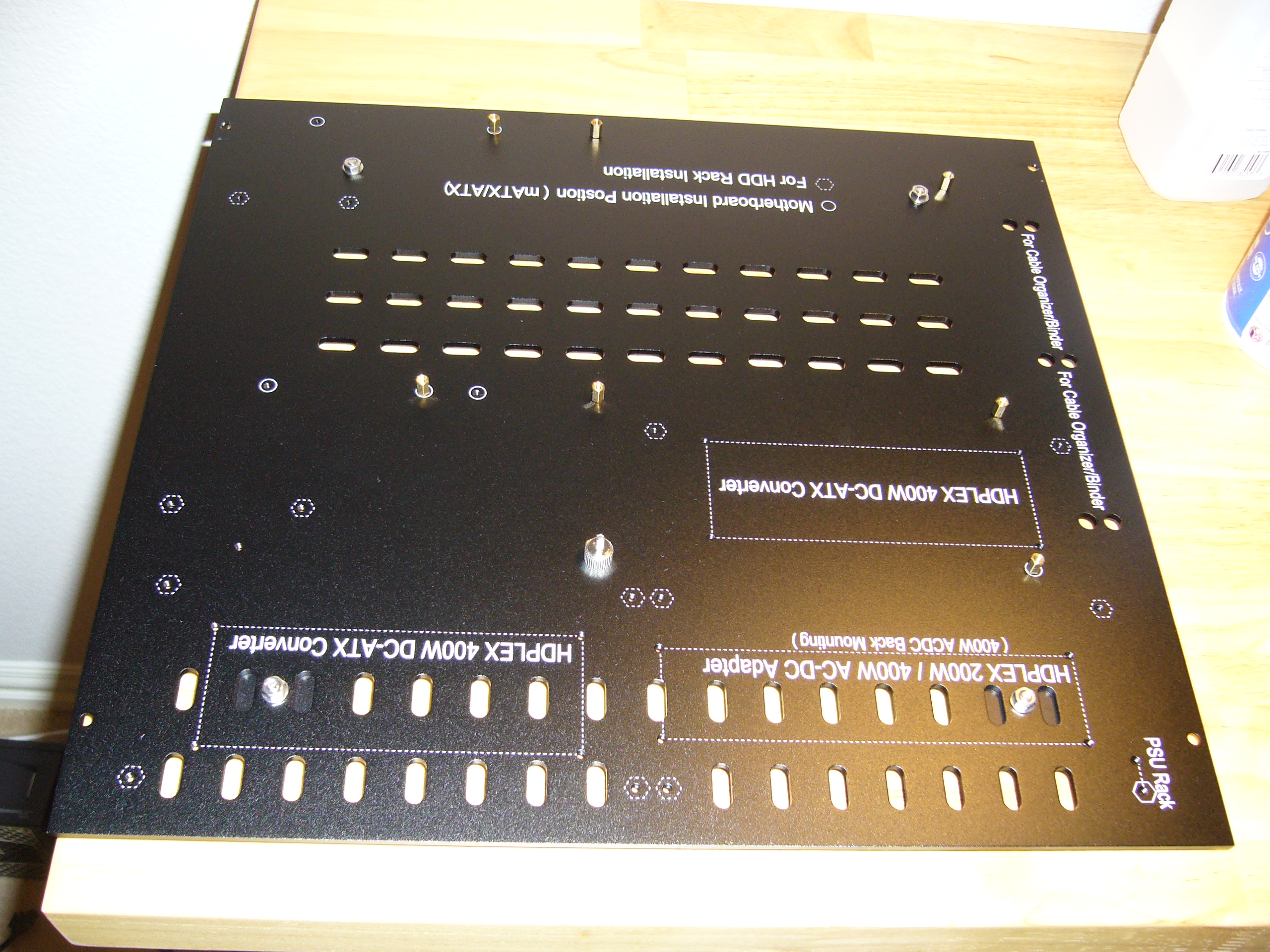
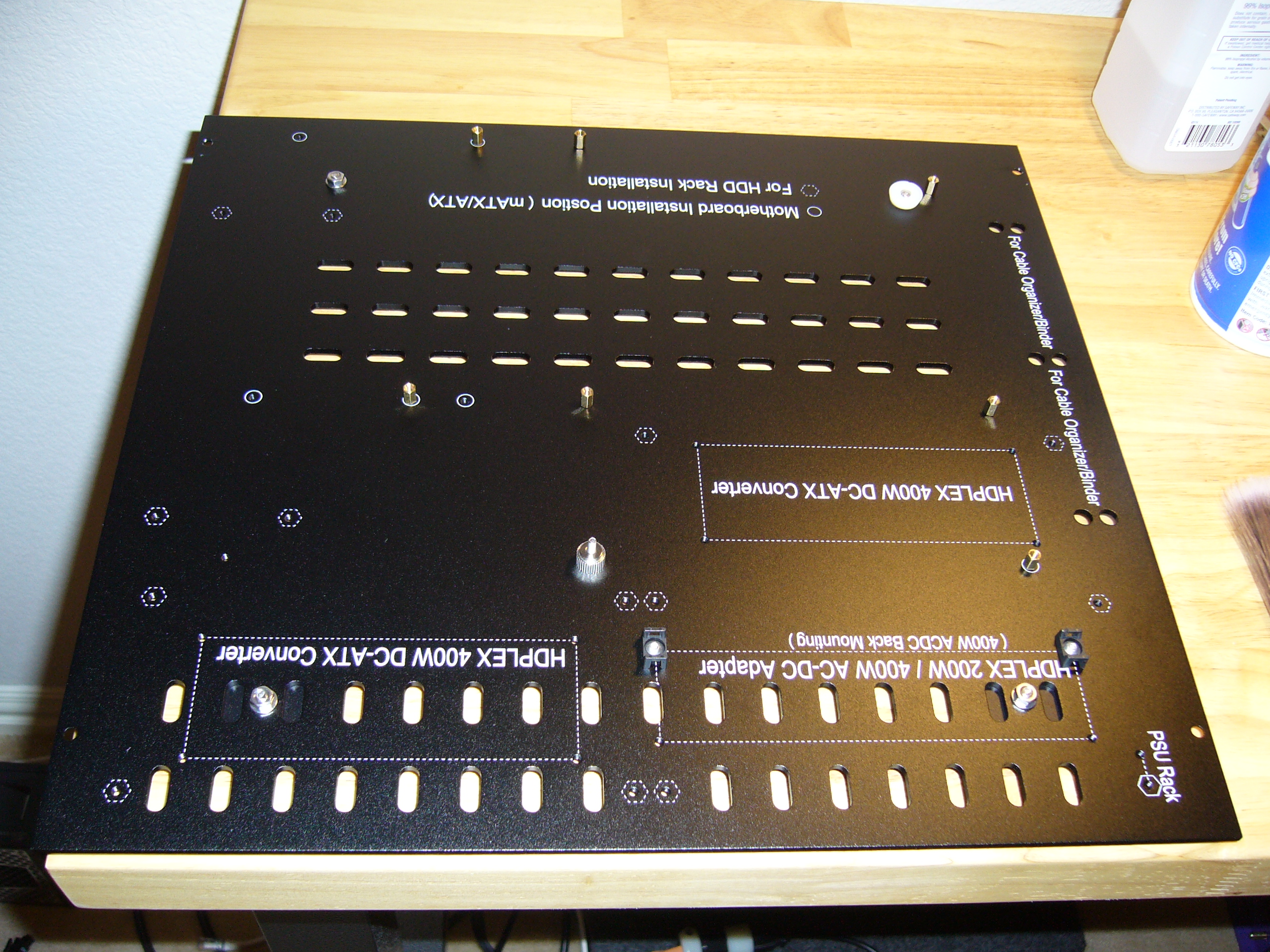
This time I am mounting both power supplies on the faceplate. I have already drilled it in the photo.
A note about the "natural finish" faceplate (in particular): It is a milled item, and this one had lots of tiny, sharp burrs on the interior edges. I cleaned them up with a deburring tool. If I was more skilled and ambitious I could have re-brushed the entire thing.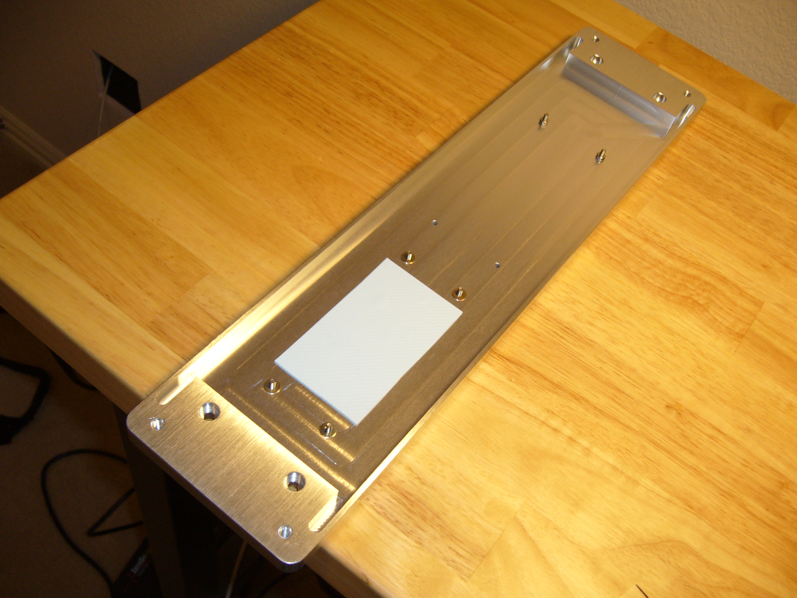 Thermal pad for the AC-24VDC power supply...
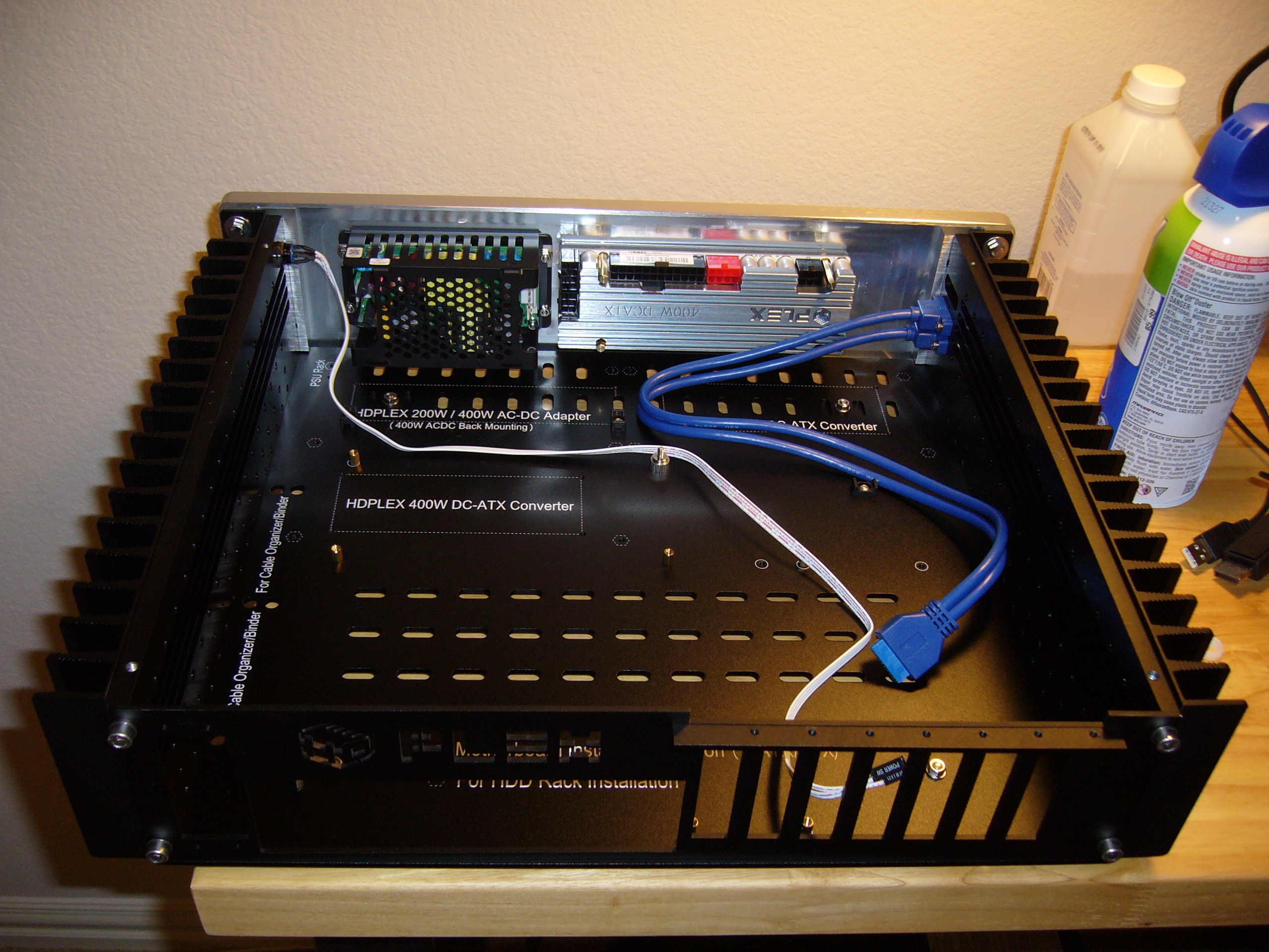
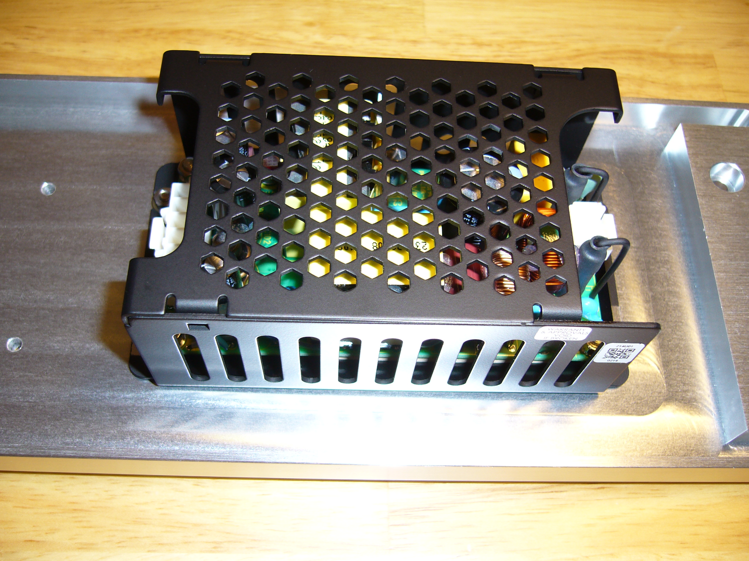 ...And the power supply, mounted.
This one is a TDK-Lambda CUS150M-24. Go figure: It is the only small power supply that I have found that has all of its power components mounted to the bottom of the circuit board and thermally coupled to the baseplate with thermal pads. So while this unit is a hot runner compared to the big Meanwell in my H5v2, it is considerably smaller, and it only heats the faceplate (and not its frame).
Incidentally, I used a 24v model (as opposed to 18V) due to availability.
If you look closely at this series of photos you can see that I plugged the connector housings into the power supply. The connectors are JST, but the form factor is a standard, fortunately. The JSTs are in short supply, but after comparing a lot of drawings I found equivalent Molex parts, which are widely available.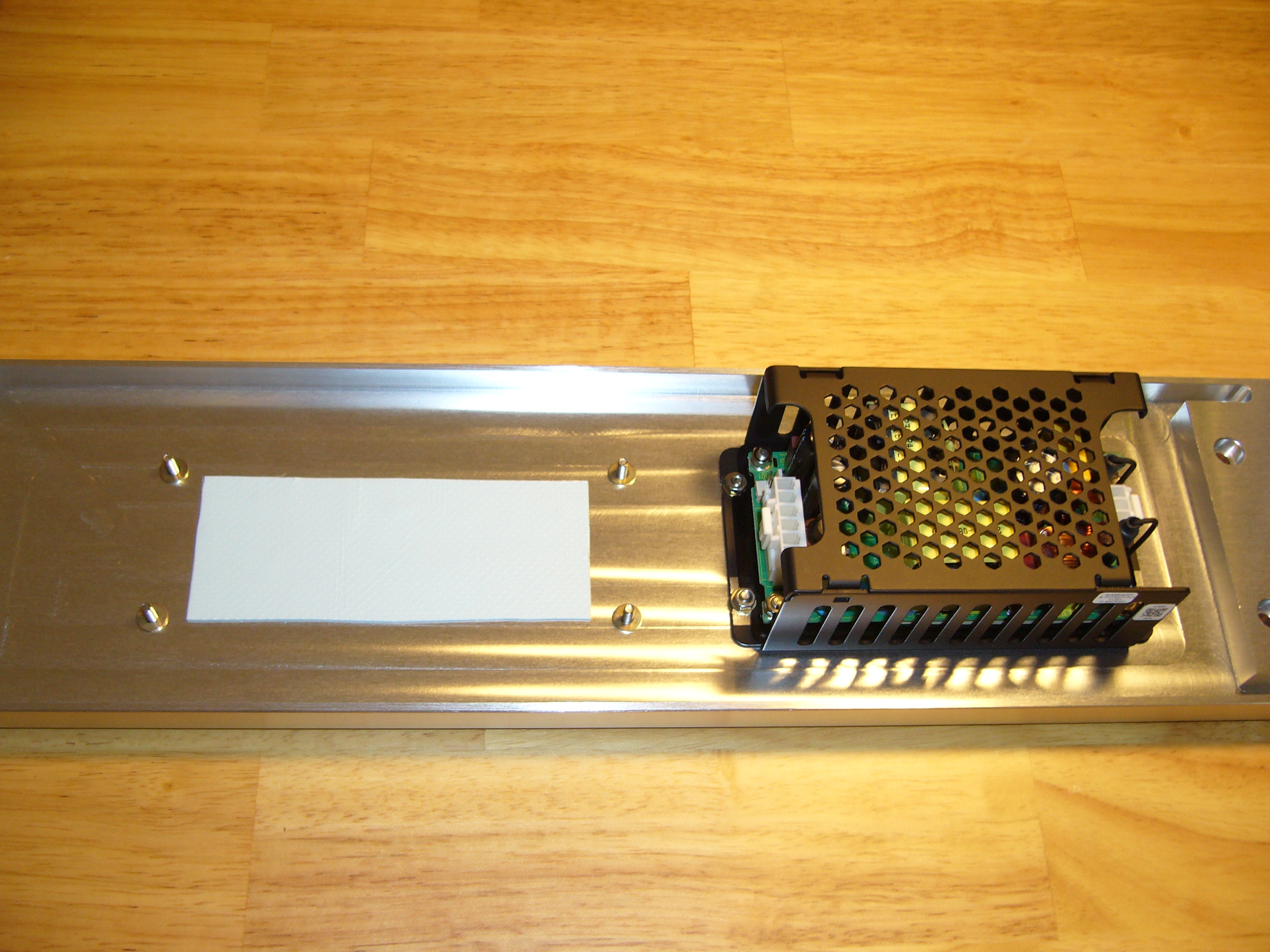 Thermal pad for the DC-ATX converter...
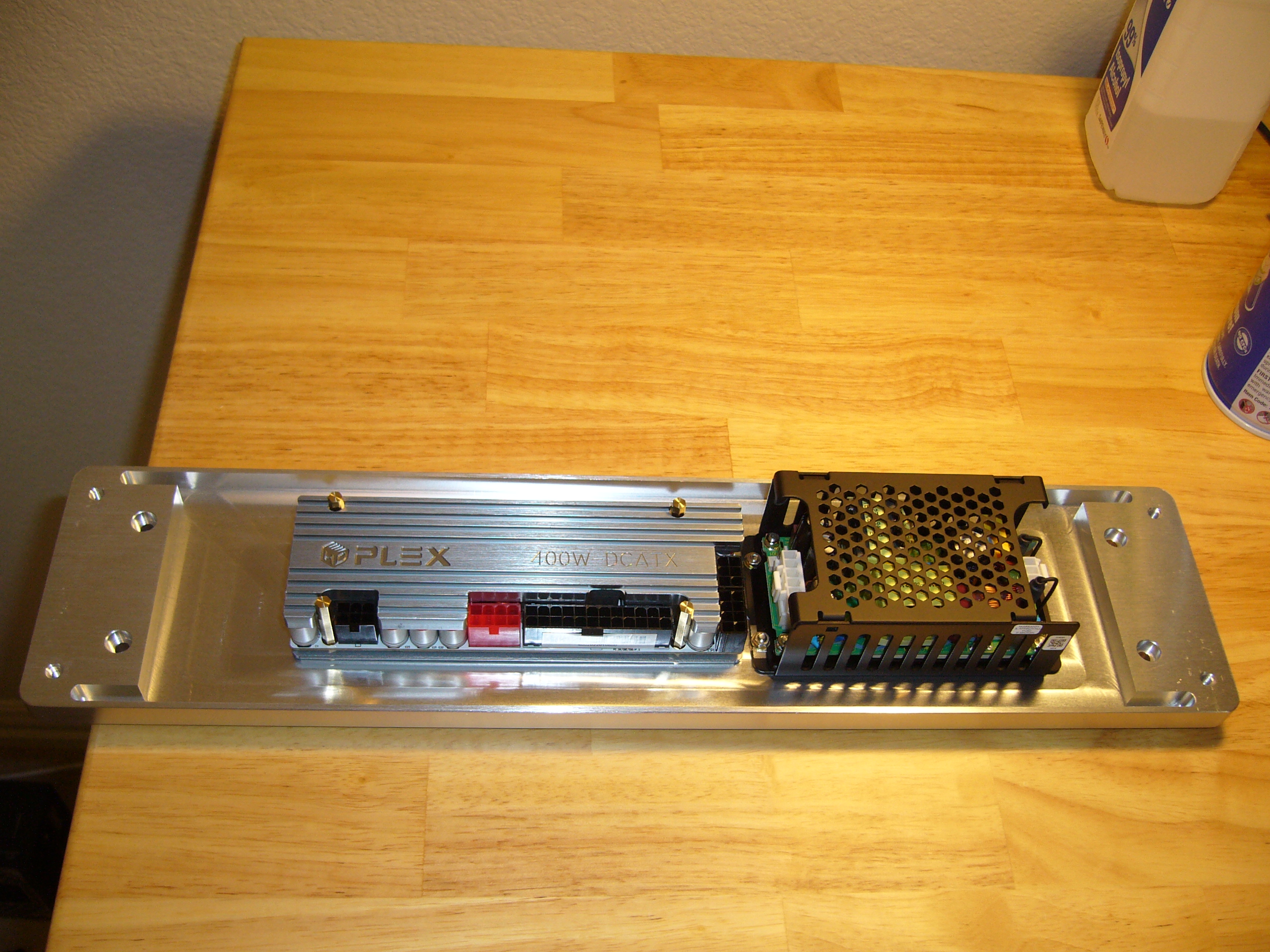 ...And the HDPlex DC-ATX converter. This is a later iteration of the same 400W model I used in my H5v2. Connector pinouts vary with version, so if
you get one of these, check the version and choose (or build) your cables appropriately.
...And the HDPlex DC-ATX converter. This is a later iteration of the same 400W model I used in my H5v2. Connector pinouts vary with version, so if
you get one of these, check the version and choose (or build) your cables appropriately.
Note that this device has most of its power components on the top of the board, so most of its generated heat will go into the interior of the enclosure. At 150W max (the rating of the AC supply), it does not generate much - it barely gets warm.
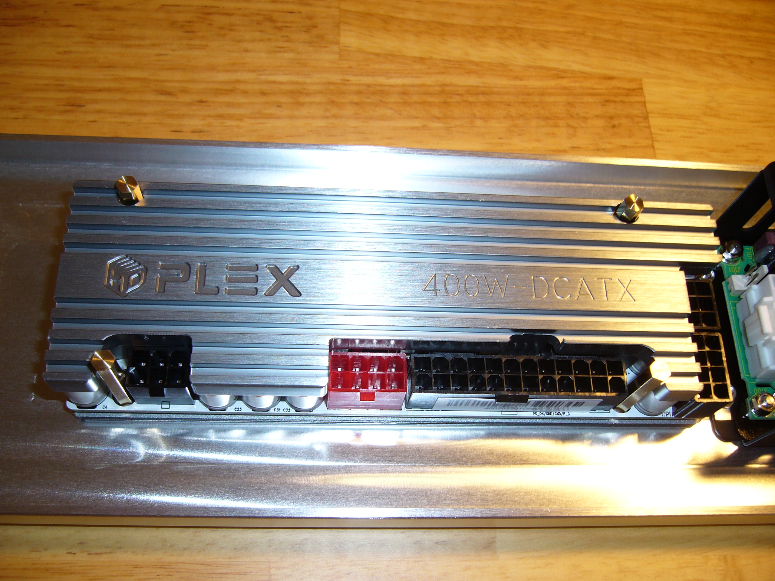
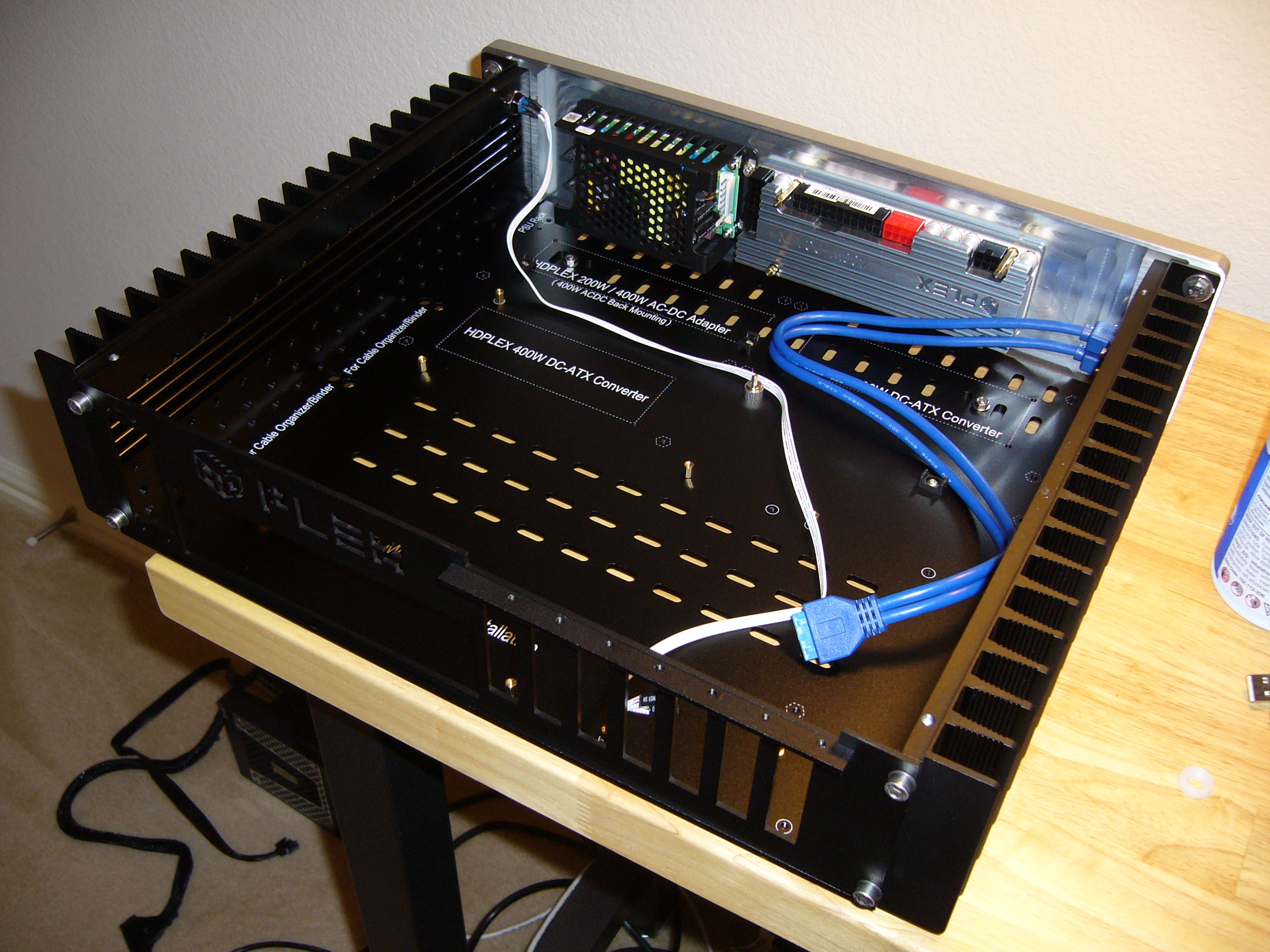
 The HDPlex converter has lots of mounting options (have a look at the spec sheets). I prefer the four through-holes, but they are heavily shrouded.
I could have run socket head screws through the converter, then through the back of the faceplace and used nuts on the exposed side, but I figured
I'd be consistent and have only screw heads showing.
The HDPlex converter has lots of mounting options (have a look at the spec sheets). I prefer the four through-holes, but they are heavily shrouded.
I could have run socket head screws through the converter, then through the back of the faceplace and used nuts on the exposed side, but I figured
I'd be consistent and have only screw heads showing.
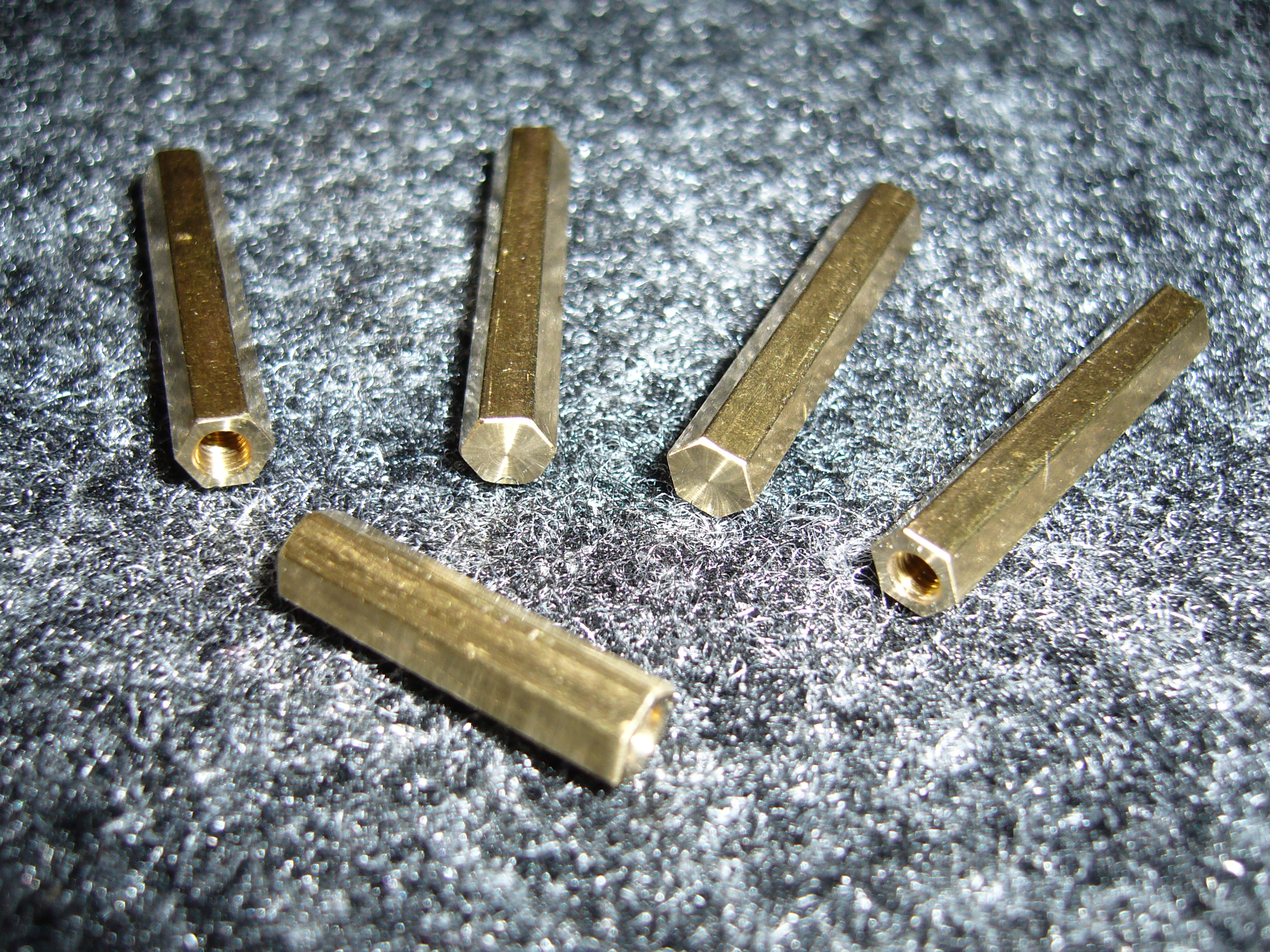
These are just brass M-F standoffs that probably came from one of my HDPlex kits, with the male screw portion lopped off. They are long enough to protrude above the top surface of the converter...
 ...Like so, so I can get a wrench on them.
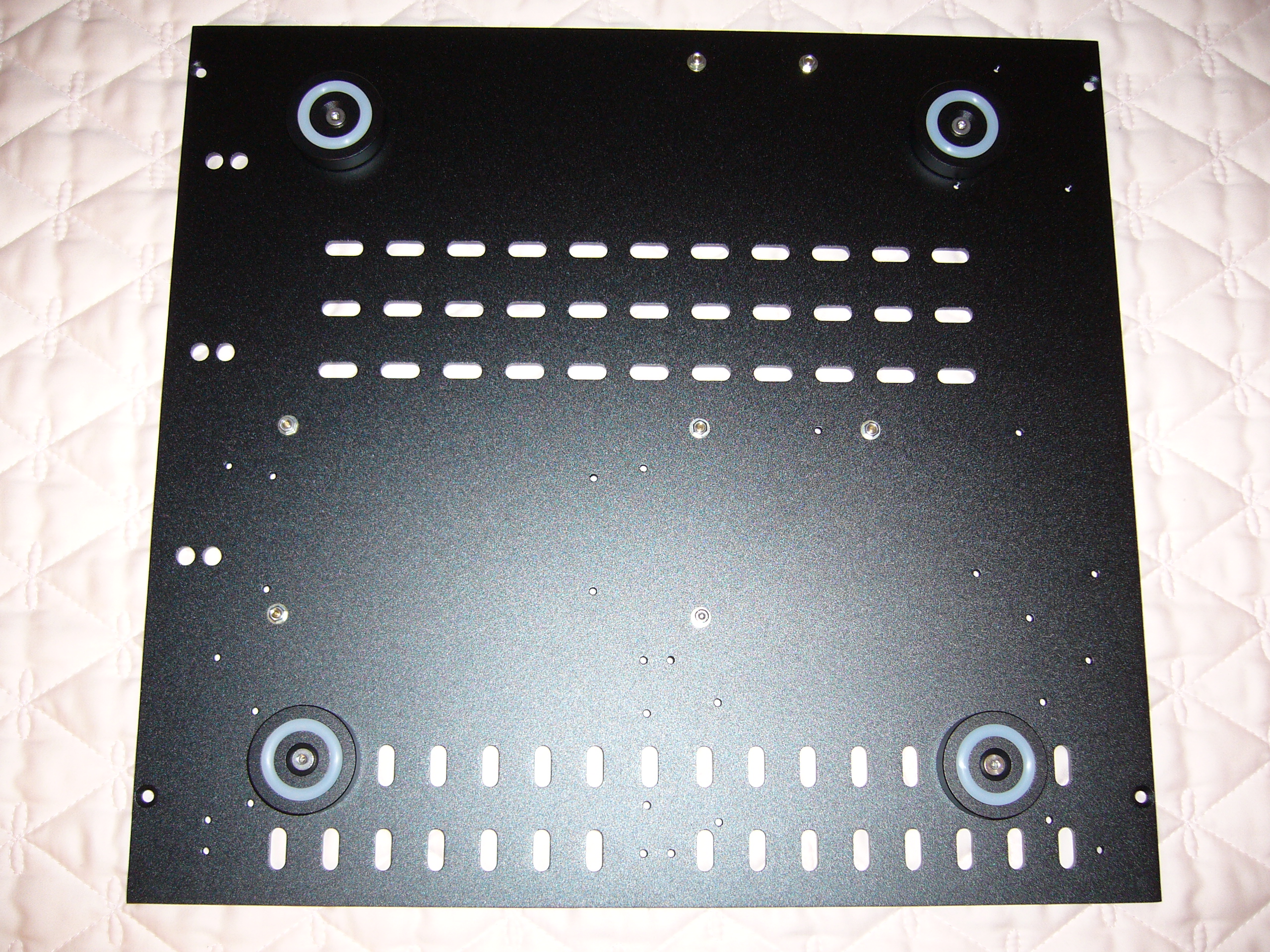 The H5v3 has the feet attached from the bottom, threaded into tapped holes in the baseplate. No more need to Loctite the screws in place!
 Ha! No Loctite, but I used longer screws and put washers and nuts on them instead. If I have failed to mention it, and you have not guessed by now,
my motto is "Anything worth doing is worth overdoing."
Ha! No Loctite, but I used longer screws and put washers and nuts on them instead. If I have failed to mention it, and you have not guessed by now,
my motto is "Anything worth doing is worth overdoing."
You may have noticed the oddball standoff. I stuck that in as a mounting point for a cable tie mount for the NVMe signal cable.
 Same view, but with an insulator placed over the foot nut in the upper right corner. In keeping with my motto, I will not risk a short.
I also added a couple cable tie mounts, using existing threaded holes in the baseplate.
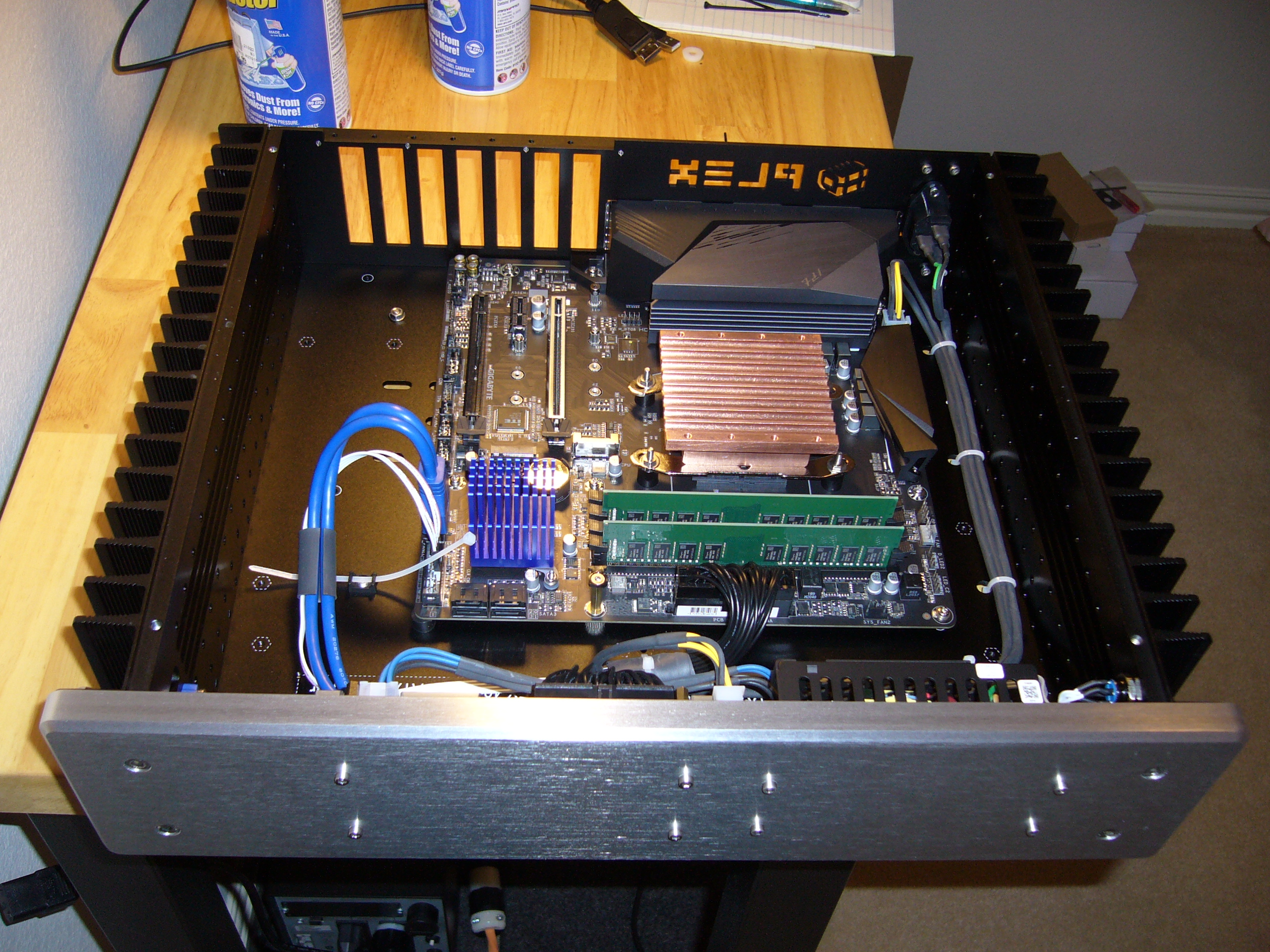
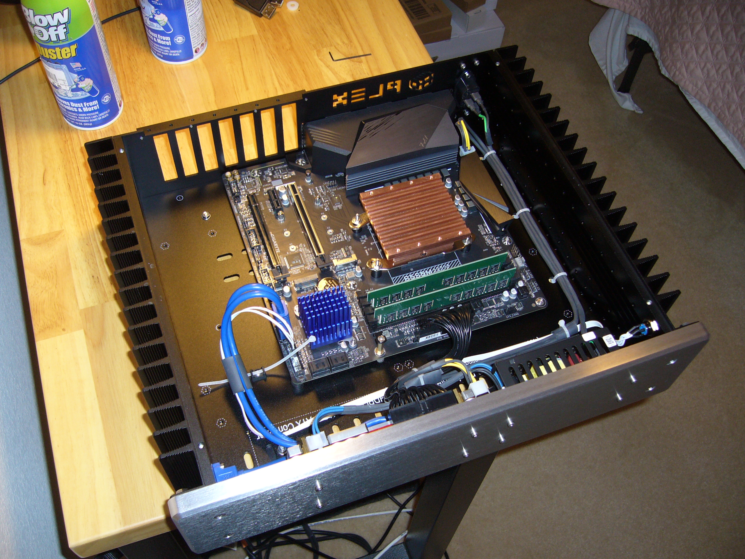
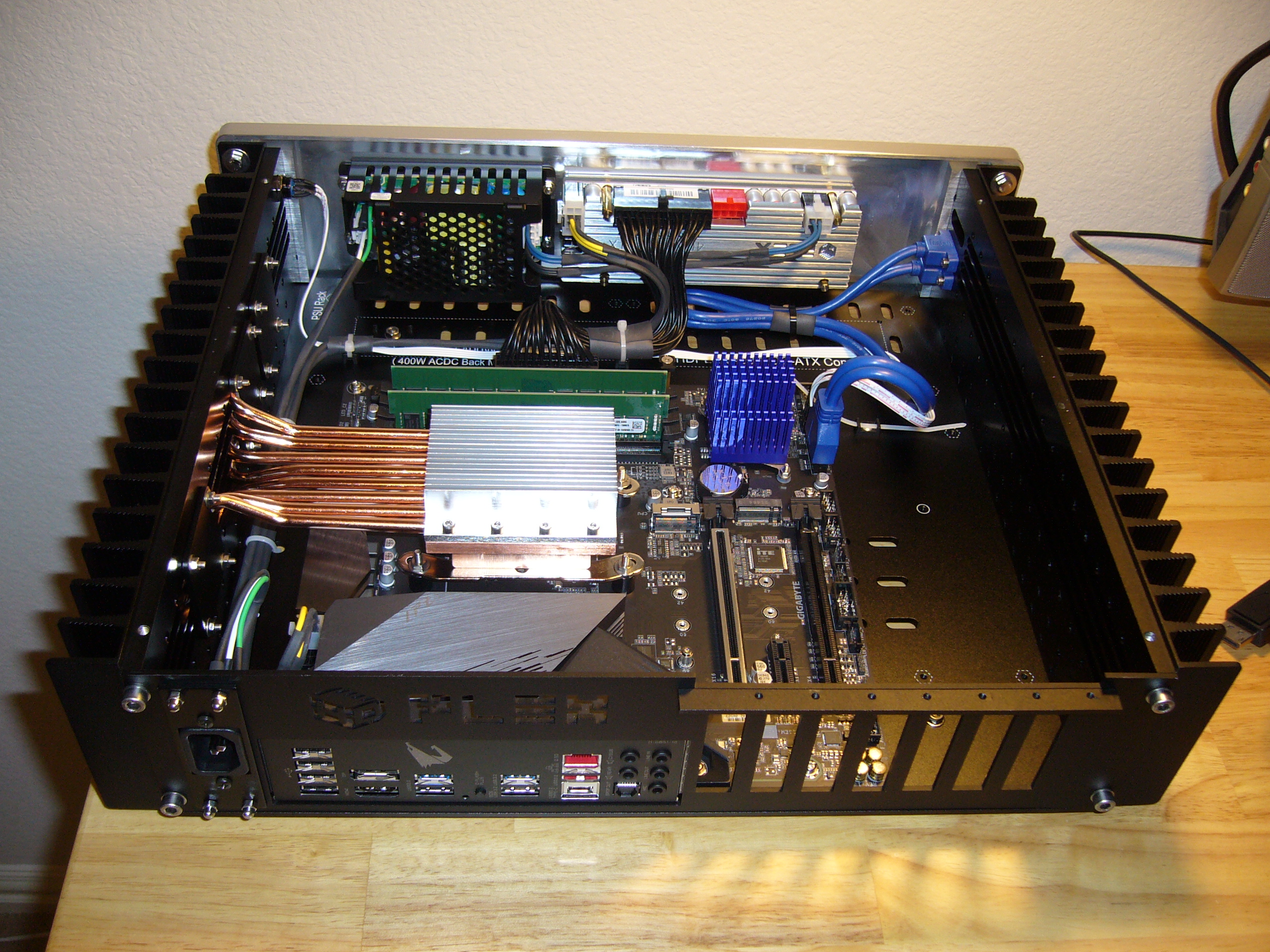
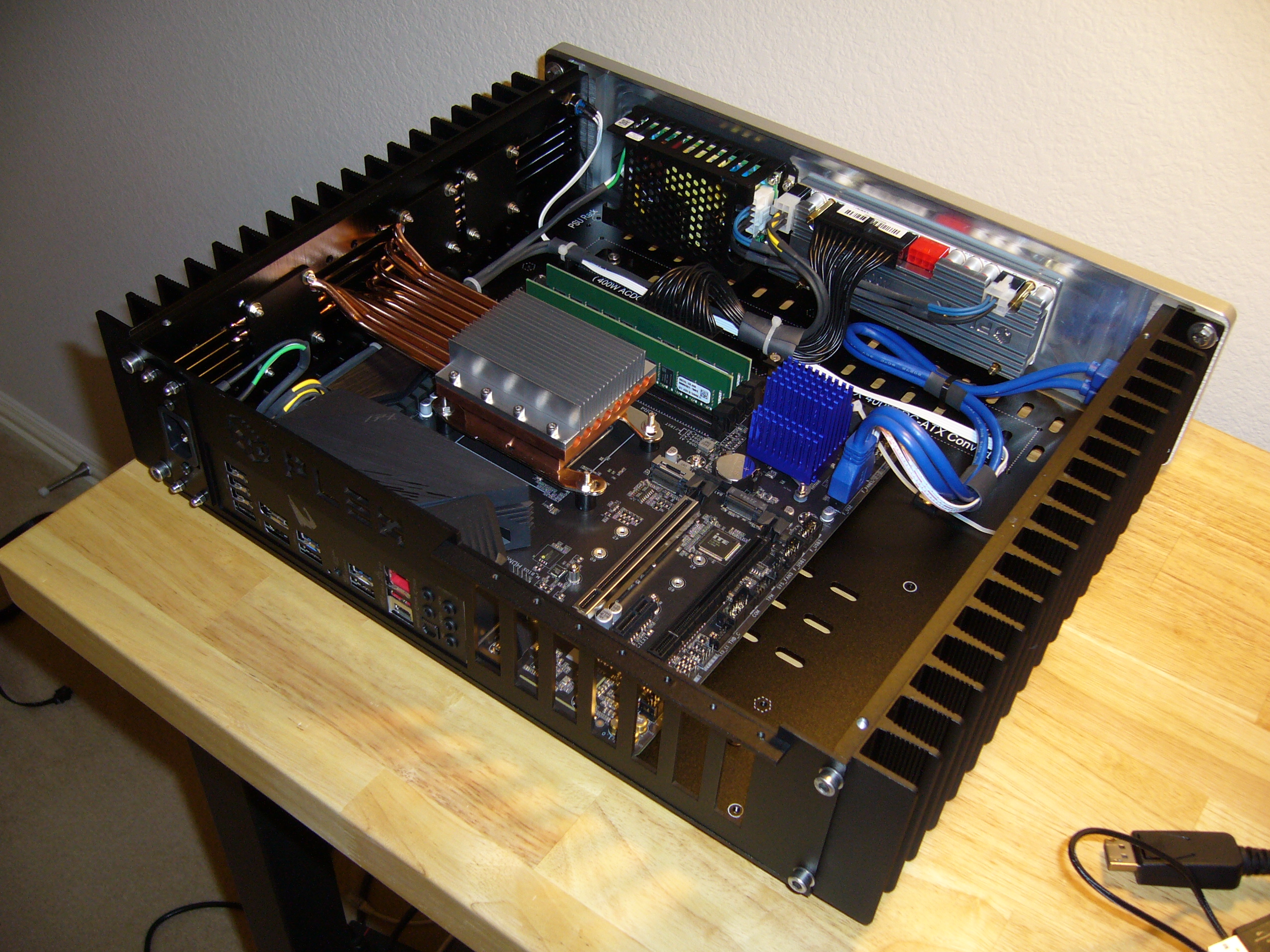
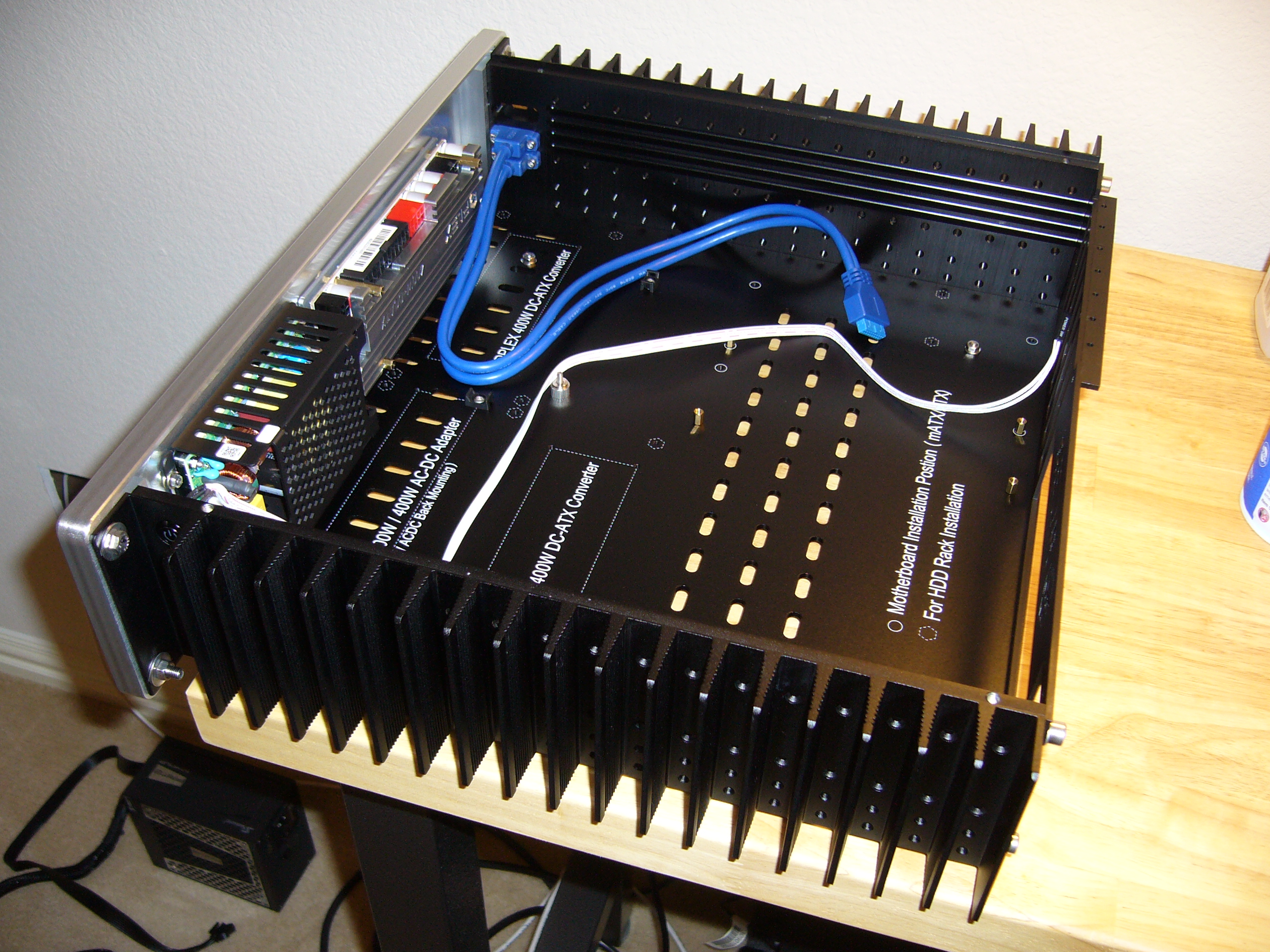 Main assembly.
Note the faceplate mounting. I ran out of M5 set screws, so I substituted a couple hex head screws for the upper pair (to clear the power button).
There is an important note on assembly that I have not gone over yet in these pages: fitting up the main assembly. I always loosely attach all sides of the enclosure - heat sinks to bottom plate, then faceplate and backplate, then (importantly) top plate. I only tighten everything once all pieces are fit together. Skip this step and chances are you will not be able to install the top plate without considerable fiddling and swearing. Even after fitting, this particular case did not want to go together - the top plate is still a tight fit. The other three do not suffer from this fitment issue.
Also note that I installed the power button and USB cables prior to installing the faceplate. I don't think I ever quite got the power button clocked vertical... there is nothing to hang onto as you turn the nut. The molded plastic USB cables do not appear to have full fastener inserts, so tightening them is a bit squishy.
There was a USB C cable included in the kit - you can see the spot for it above the USB A cables - but the motherboard did not have a matching connector.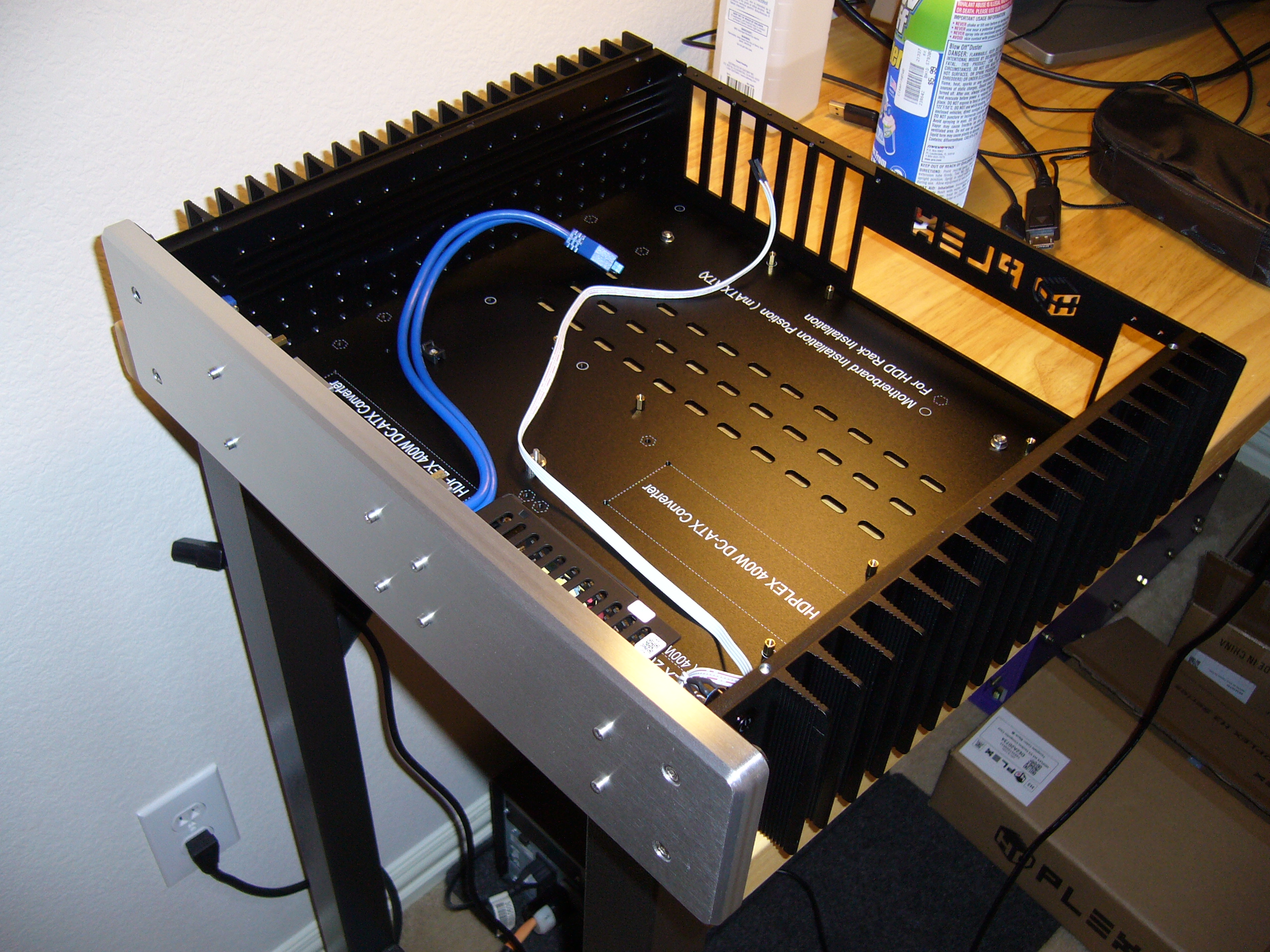
 This model, like the H3v3, has the four additional faceplate mounting screw positions.
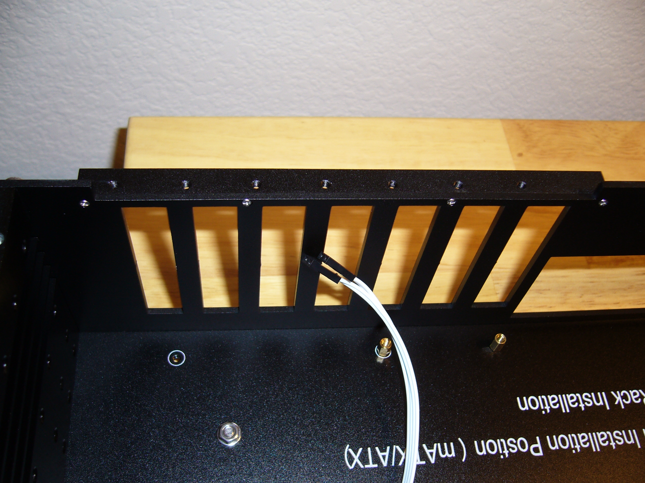 This model uses a very different backplate design. What would normally be a stamped-over flange for expansion card mounting is a 3mm bar fastened
with M2 screws. Not a method I would have considered. I did remove the screws and countersink the holes a bit, as the heads were protruding above
the surface.
This model uses a very different backplate design. What would normally be a stamped-over flange for expansion card mounting is a 3mm bar fastened
with M2 screws. Not a method I would have considered. I did remove the screws and countersink the holes a bit, as the heads were protruding above
the surface.
This backplate design makes expansion card installation easy (due to the lack of shrouding over the top of the card cage), but less secure. The stamped-in retainers for the bottom of the card brackets have been deleted, and since the overall backplate is a flat sheet, it is much less stiff than in prior models. So you have to handle it carefully - if you bend it even slightly it will negatively affect fitment. It also has no attachment to the top or bottom plates, which is unfortunate given its overall weakness.
 Close view of the insulator over the foot mounting screw and nut.
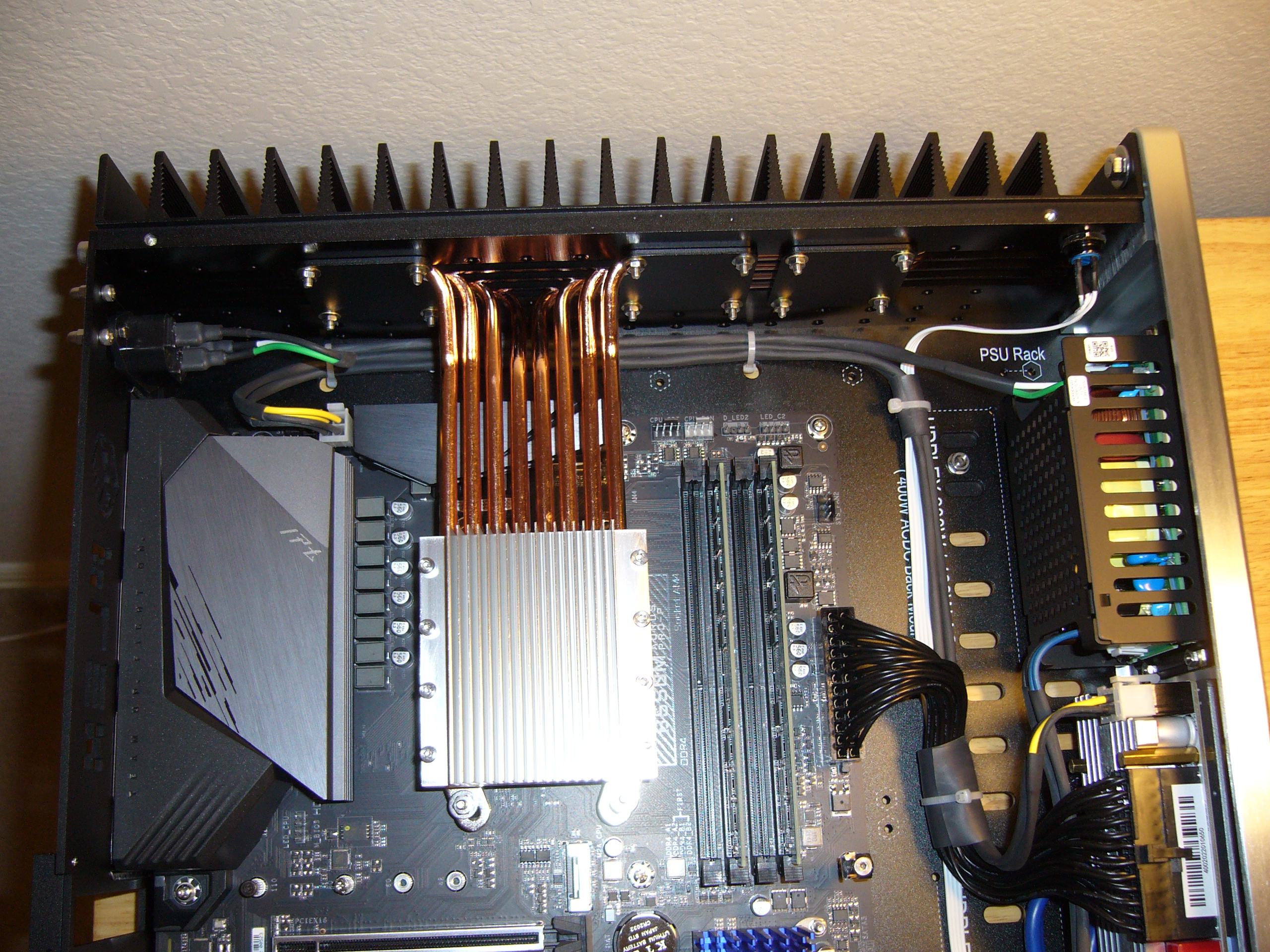
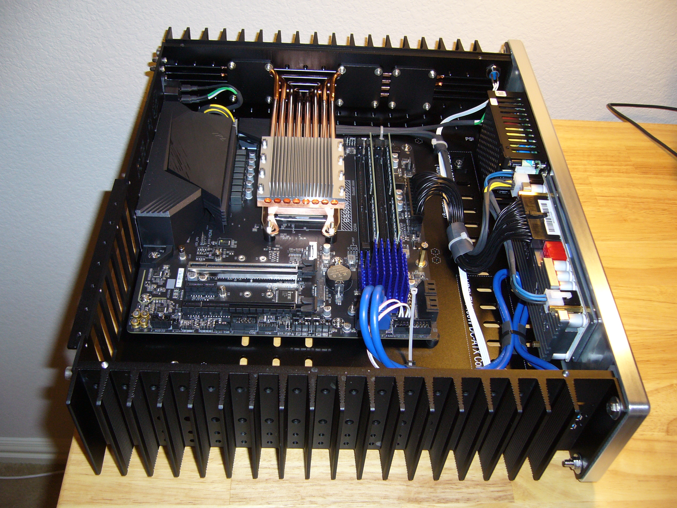
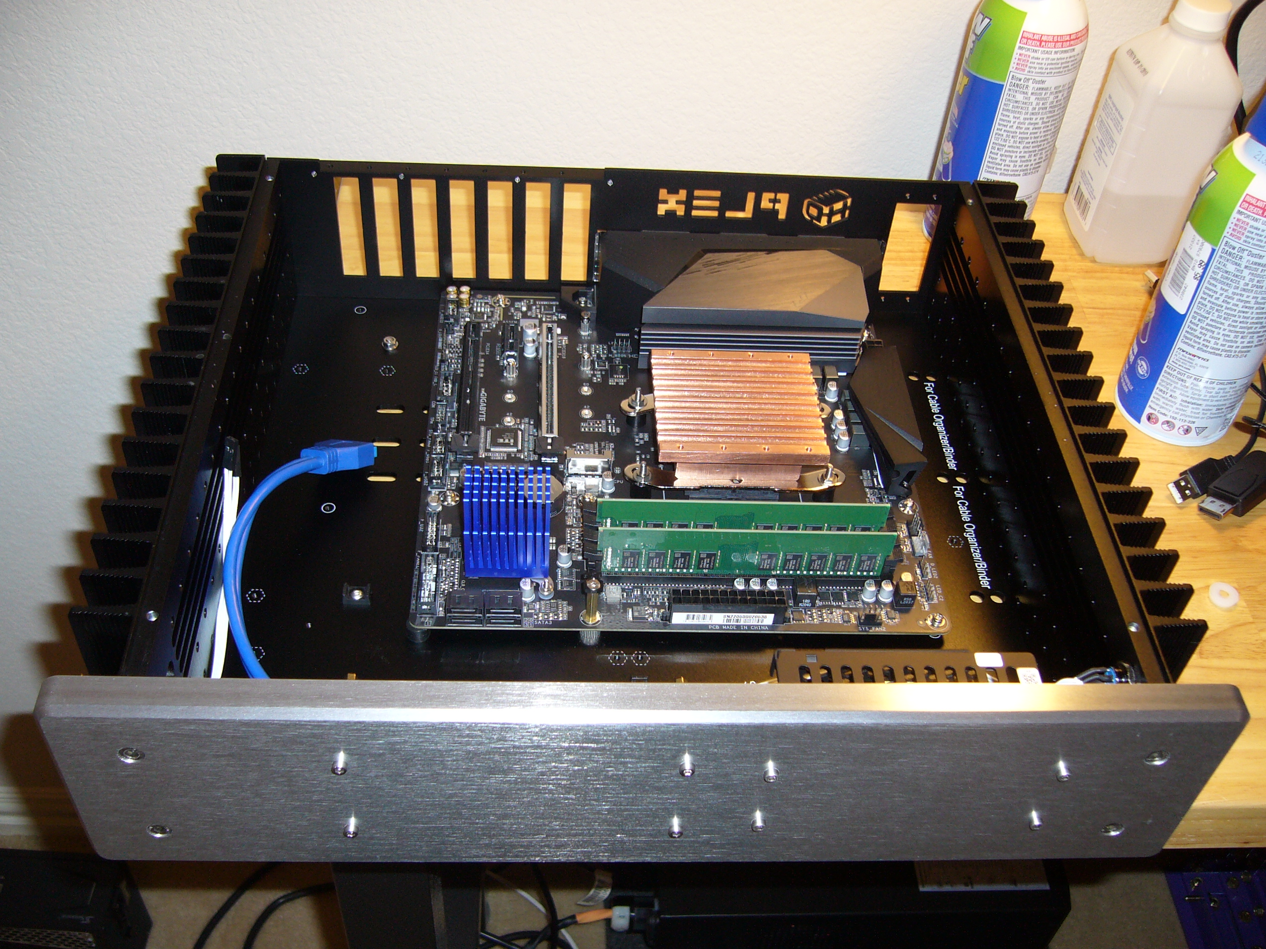 Now the motherboard is installed. You can see the custom cable tie mount on the standoff inline with the CPU M.2 slot. I also placed a silicone
stick-on bumper in the chipset corner of the motherboard to keep it from flexing. There are one or two others underneath the socket area to help
support the heavy CPU block.
Now the motherboard is installed. You can see the custom cable tie mount on the standoff inline with the CPU M.2 slot. I also placed a silicone
stick-on bumper in the chipset corner of the motherboard to keep it from flexing. There are one or two others underneath the socket area to help
support the heavy CPU block.
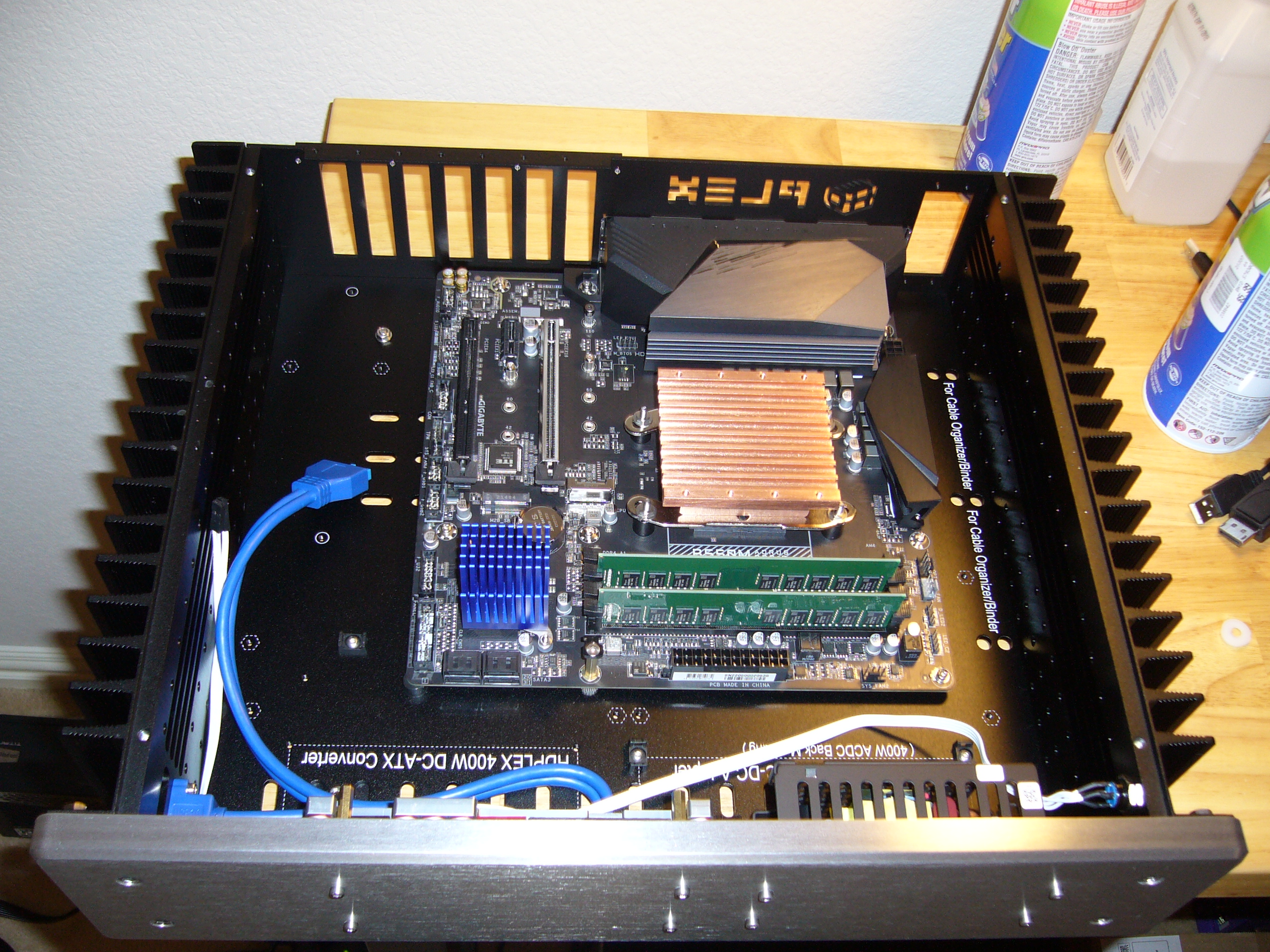
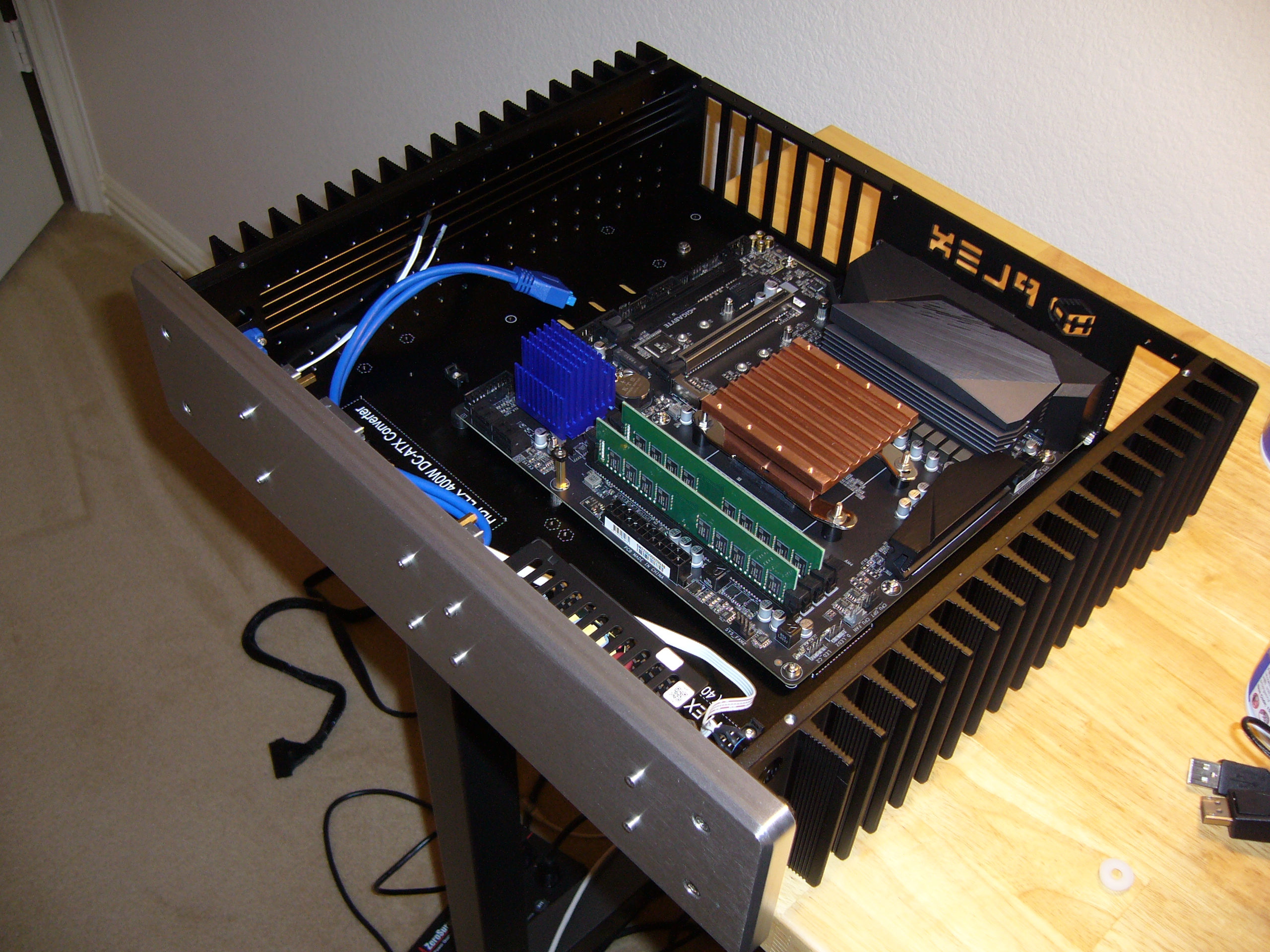
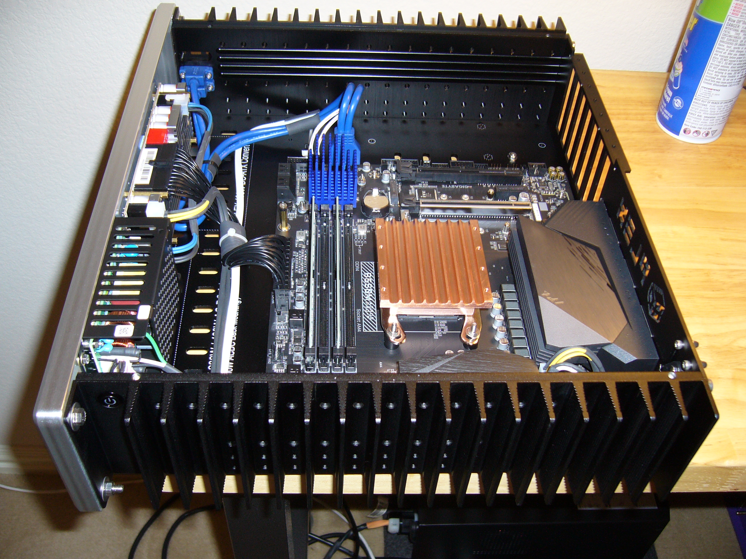 Cable layout and installation. As usual, I made my own power cables (aside from the ATX 24-pin power).
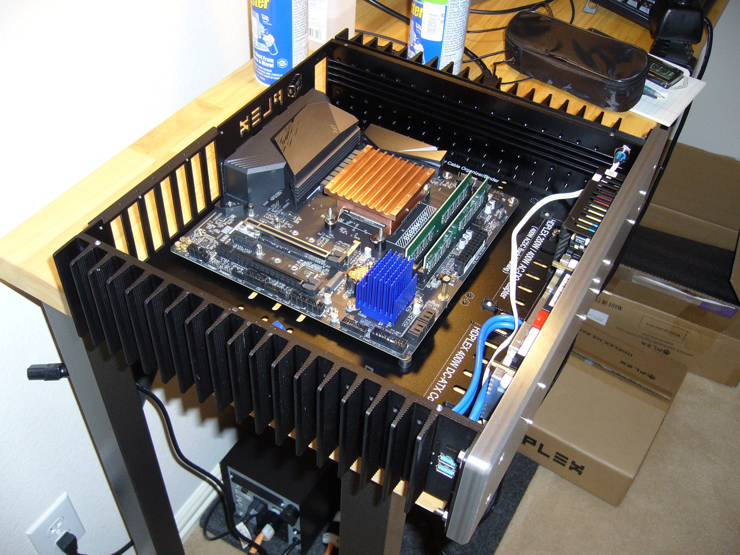
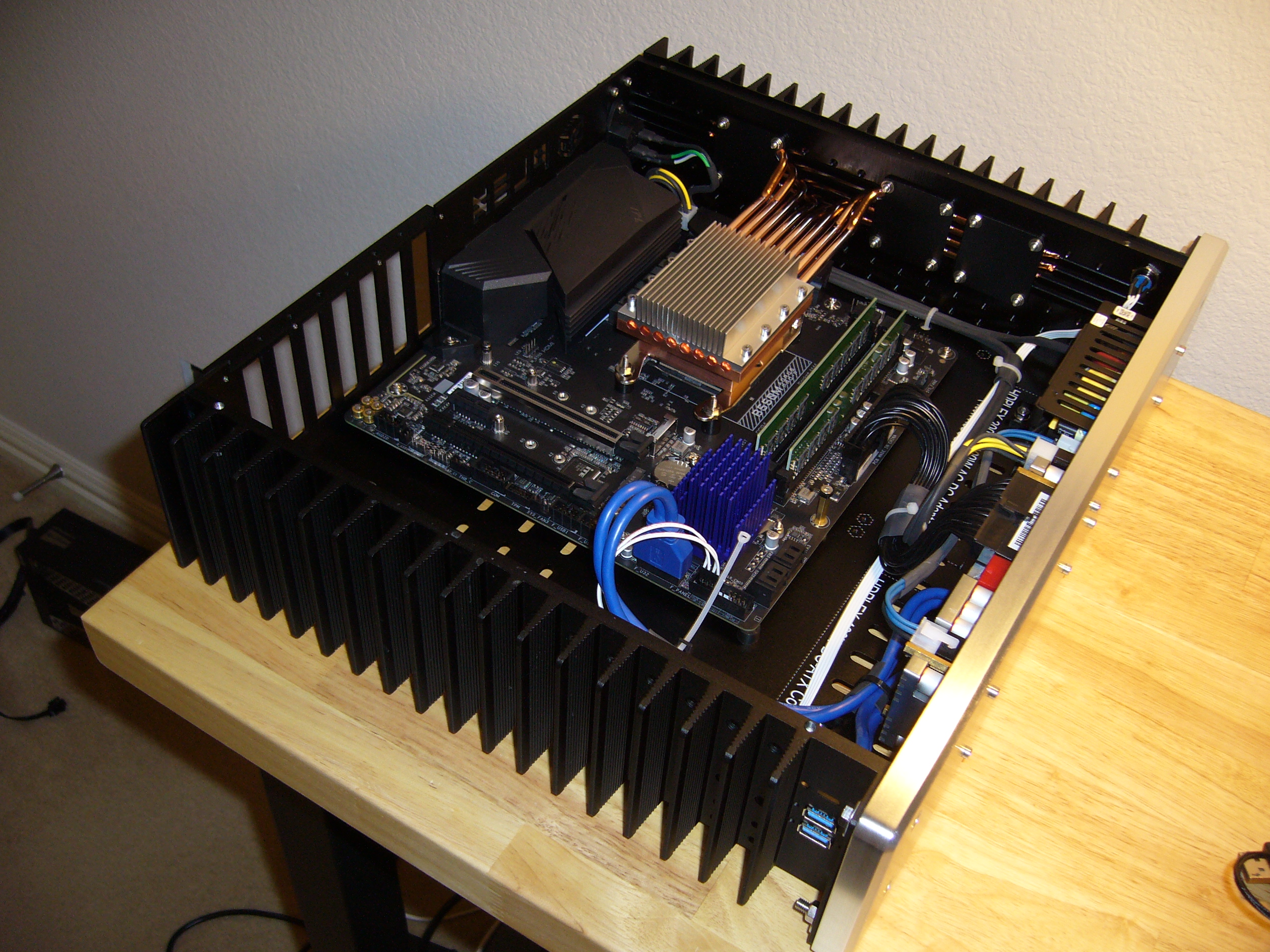
 Time to install the heat pipes. For more detail, see the H5v2 page.
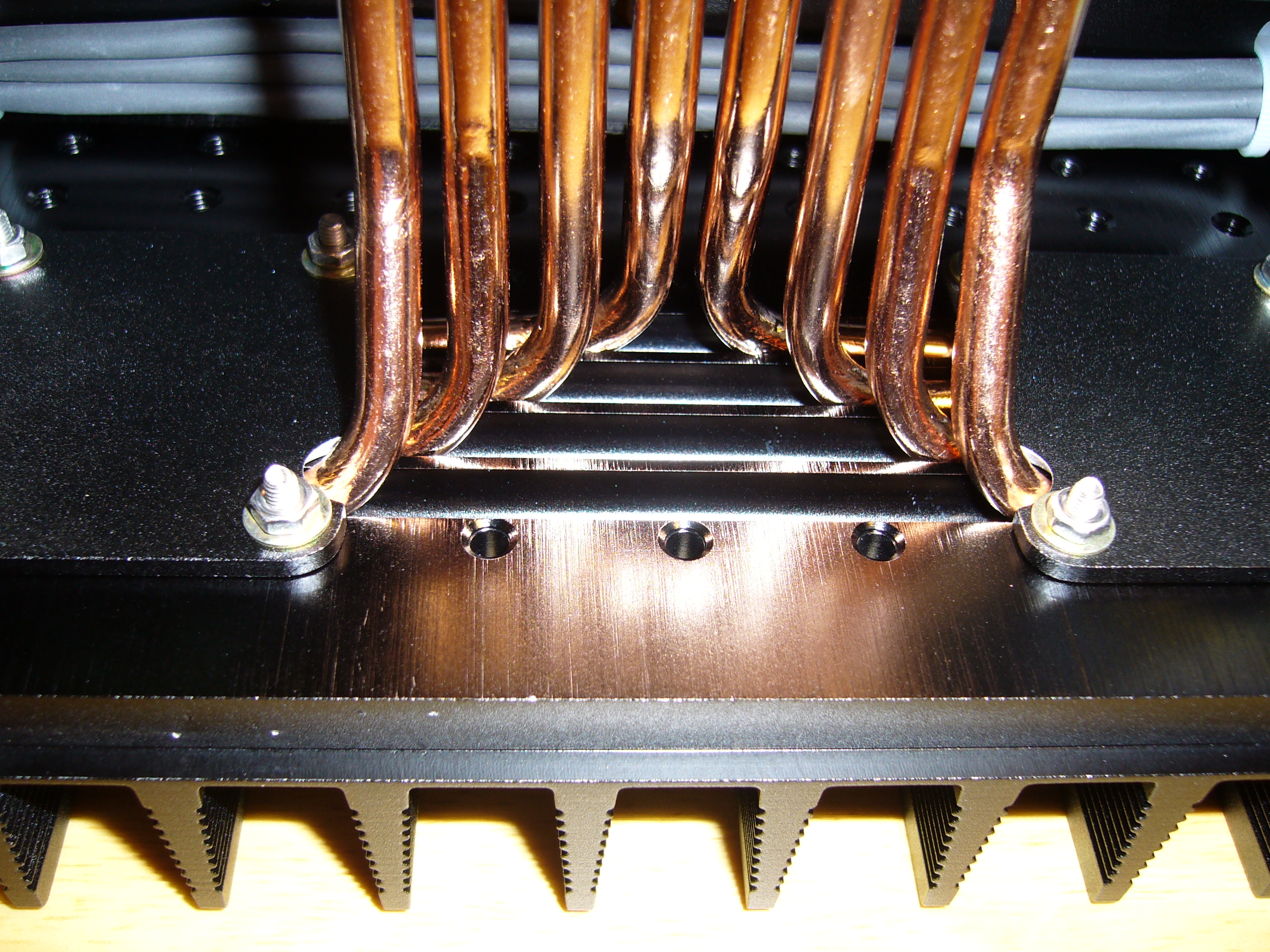 Well, some bad luck and a solution.
Come to find out the CPU socket on this board lands it right smack between the heat pipe retainer positions. On both sides. Sure, I could have simply moved the retainers one step outward, but I would be left with a lot of heat pipes with little retention and a lot of air with plenty of retention. Now, after having bought four of these enclosures, I have enough spare heat pipe retainer plates that I can afford to chop up a few, so I did. After a bit of filing and sanding, these fit fine. Only the upper/outermost heat pipes required a notch.
Folks with less experience might consider going at something like this with a rotary tool. After all, you want a round notch. Just remember that your rotary tool can exert quite a bit of force where the tool meets the part, so unless you have both tool and part firmly secured in relation to one another, you may have... control issues. I prefer hand tools for this kind of job, and it is tough enough getting a file to start a notch where you want it.
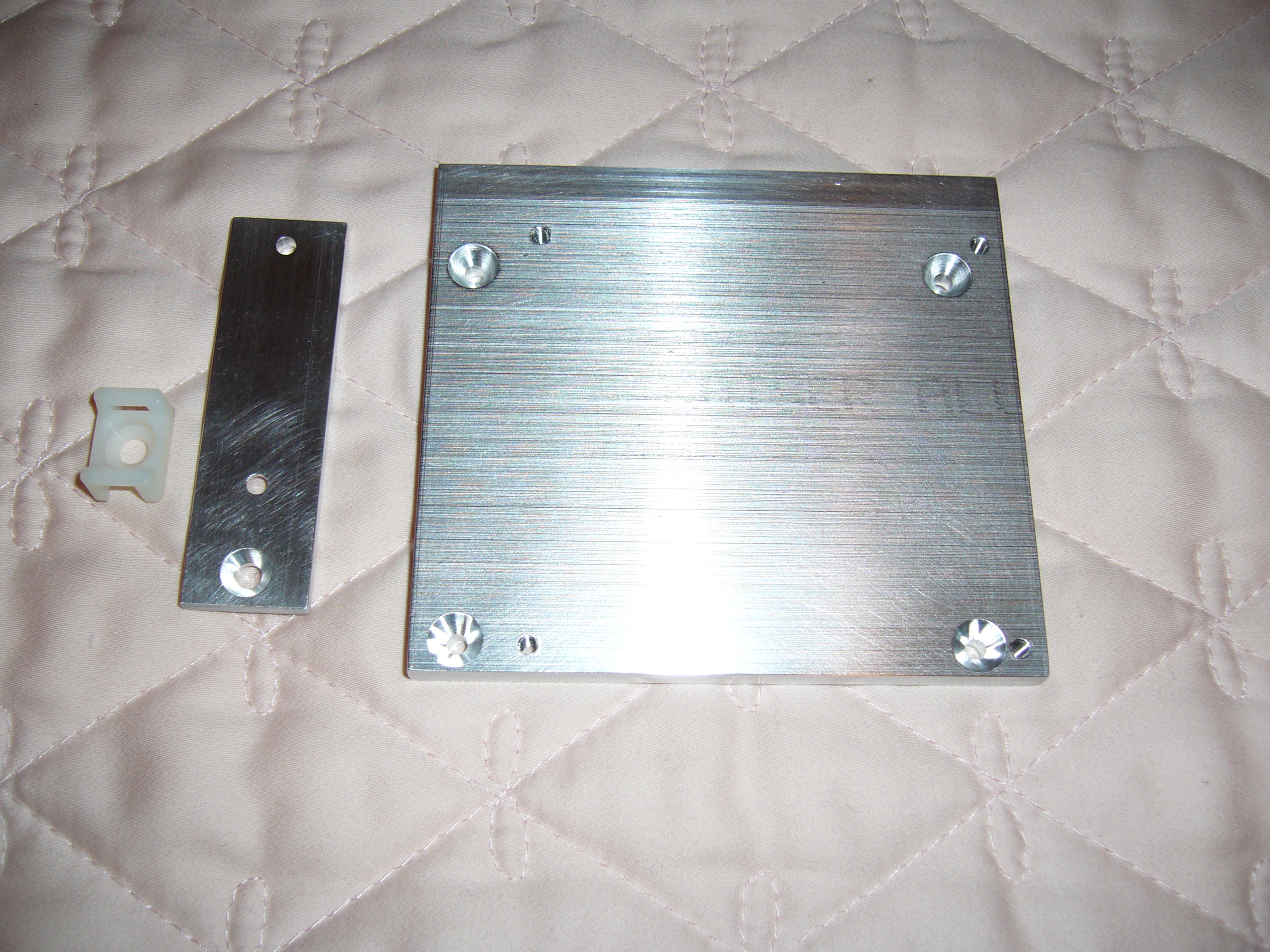 Here is the SSD mount I fabricated for this enclosure, along with its companion mount for the cable tie mount. I managed to photograph the back side
of the former with the front side of the latter.
Here is the SSD mount I fabricated for this enclosure, along with its companion mount for the cable tie mount. I managed to photograph the back side
of the former with the front side of the latter.
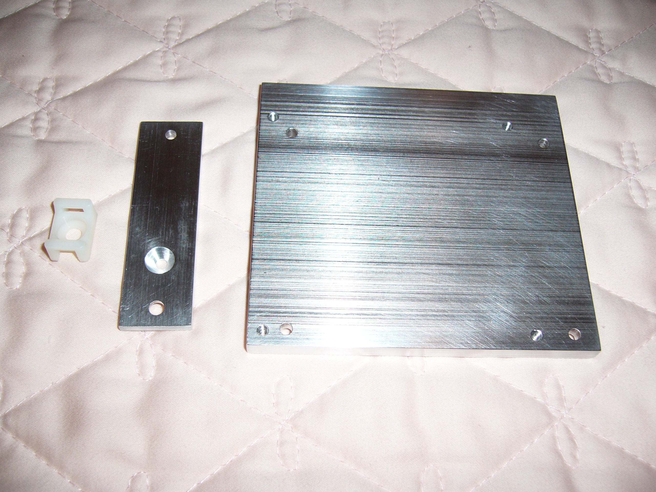 And the opposite sides of each.
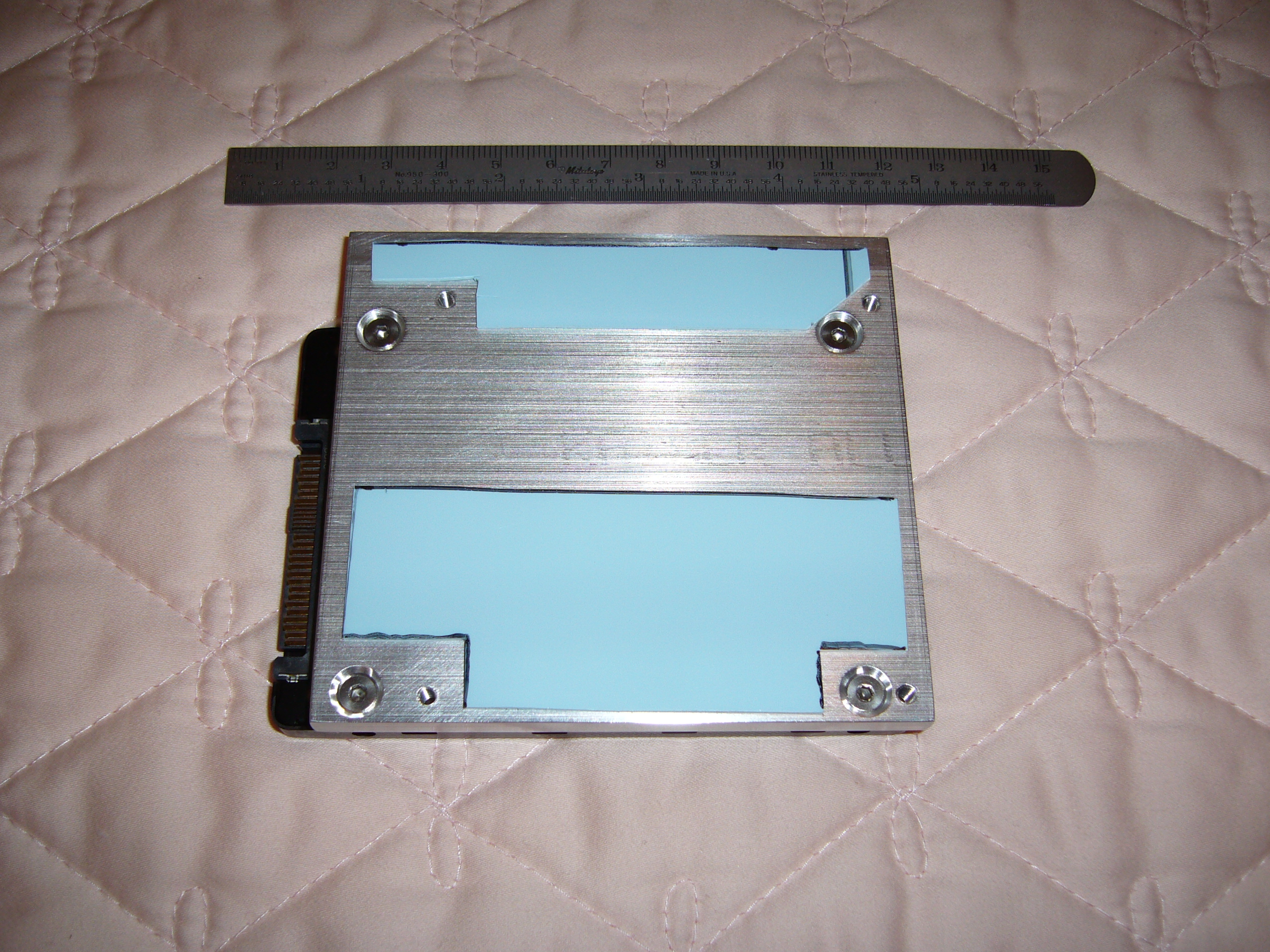
 The SSD mount with the SSD mounted.
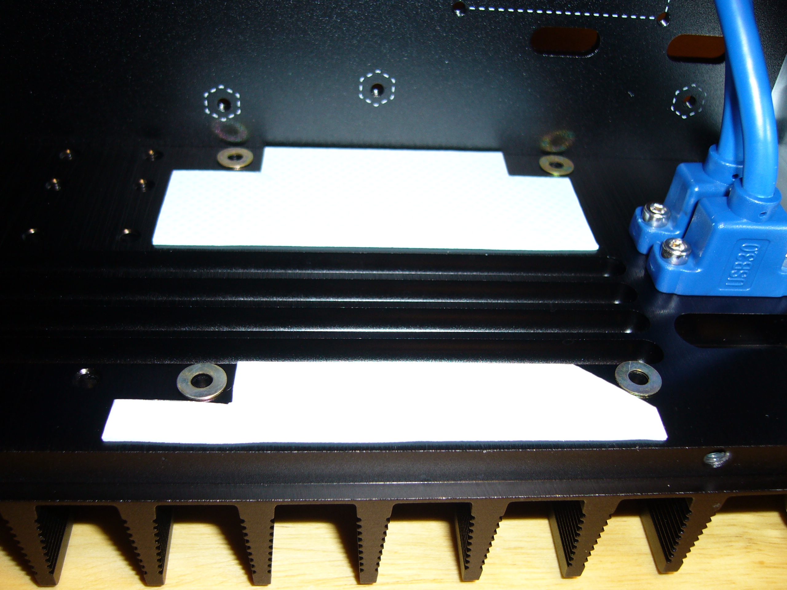
 Thermal pad layout. The gap corresponds to the heat pipe grooves in the heat sink...
 ...As you can see here. It may not seem like much area (and it could be better), but the SSD is only a 12W device.
 Washer placement.
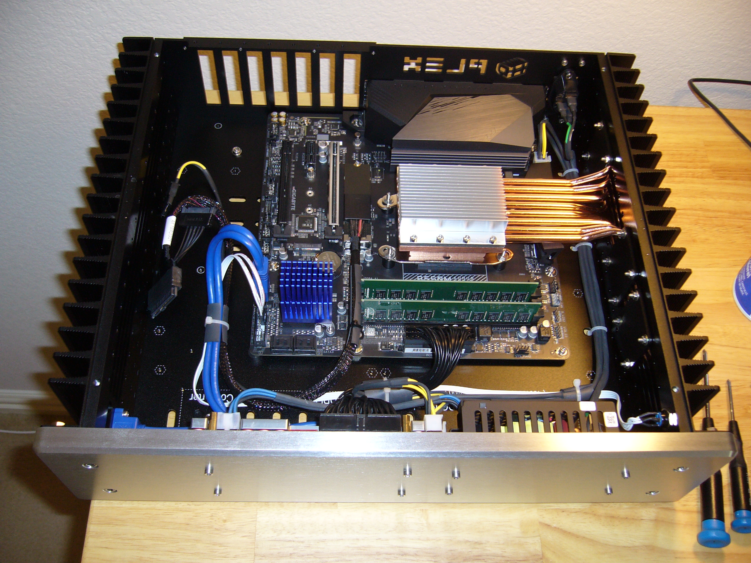
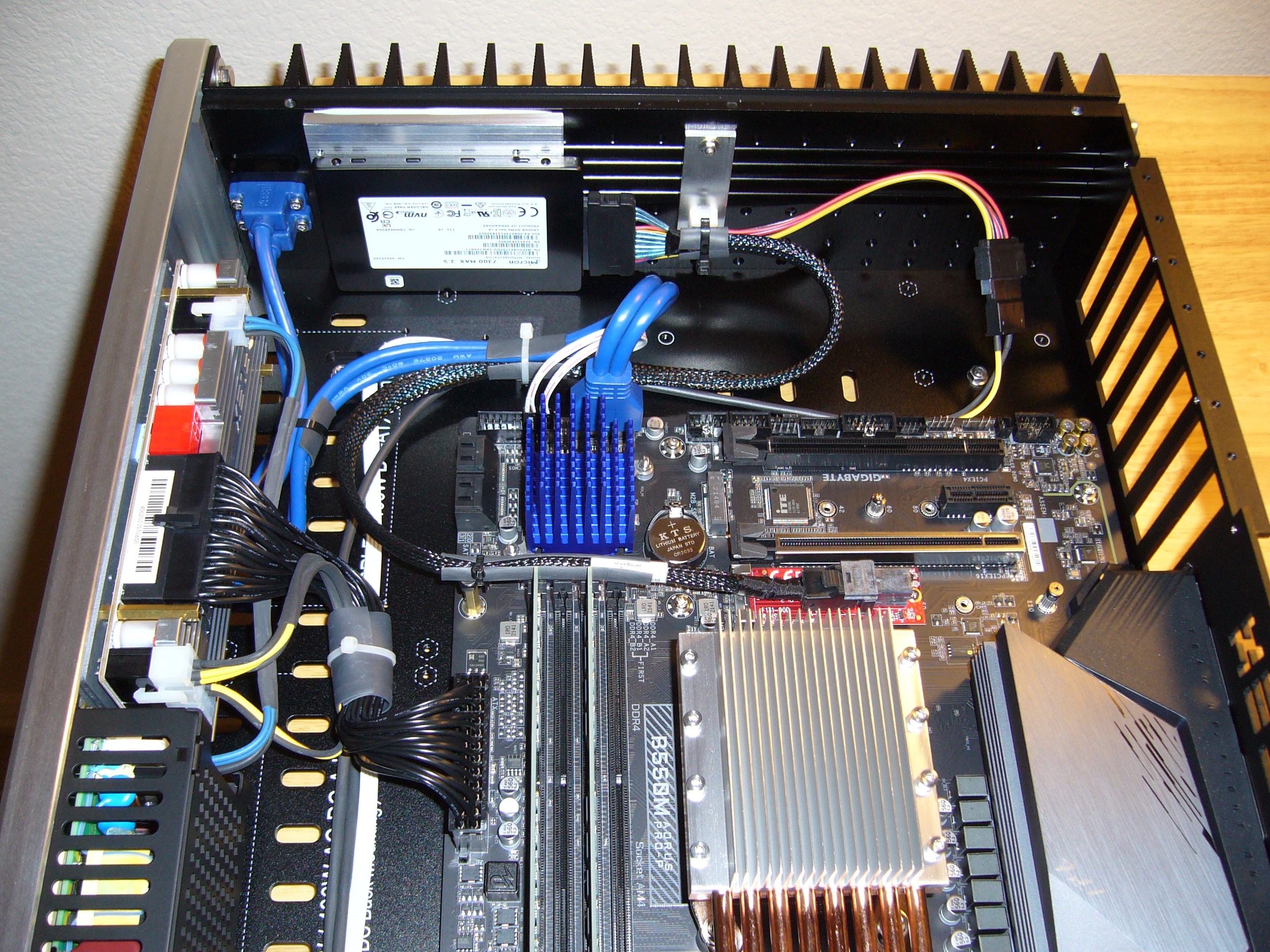 After much fiddling with washers, the SSD is in place, plugged in, and its cable secured. It is a Micron 7300 Max, by the way. I only ran 12V power,
as that is all that is required. If you do the same, check the negative wiring in the power section of your cable and use the appropriate contacts -
you do not want your device to reference its negative through the signal cable. Speaking of the cable, it is a Highpoint, while the M.2 adapter is a
Startech.
After much fiddling with washers, the SSD is in place, plugged in, and its cable secured. It is a Micron 7300 Max, by the way. I only ran 12V power,
as that is all that is required. If you do the same, check the negative wiring in the power section of your cable and use the appropriate contacts -
you do not want your device to reference its negative through the signal cable. Speaking of the cable, it is a Highpoint, while the M.2 adapter is a
Startech.
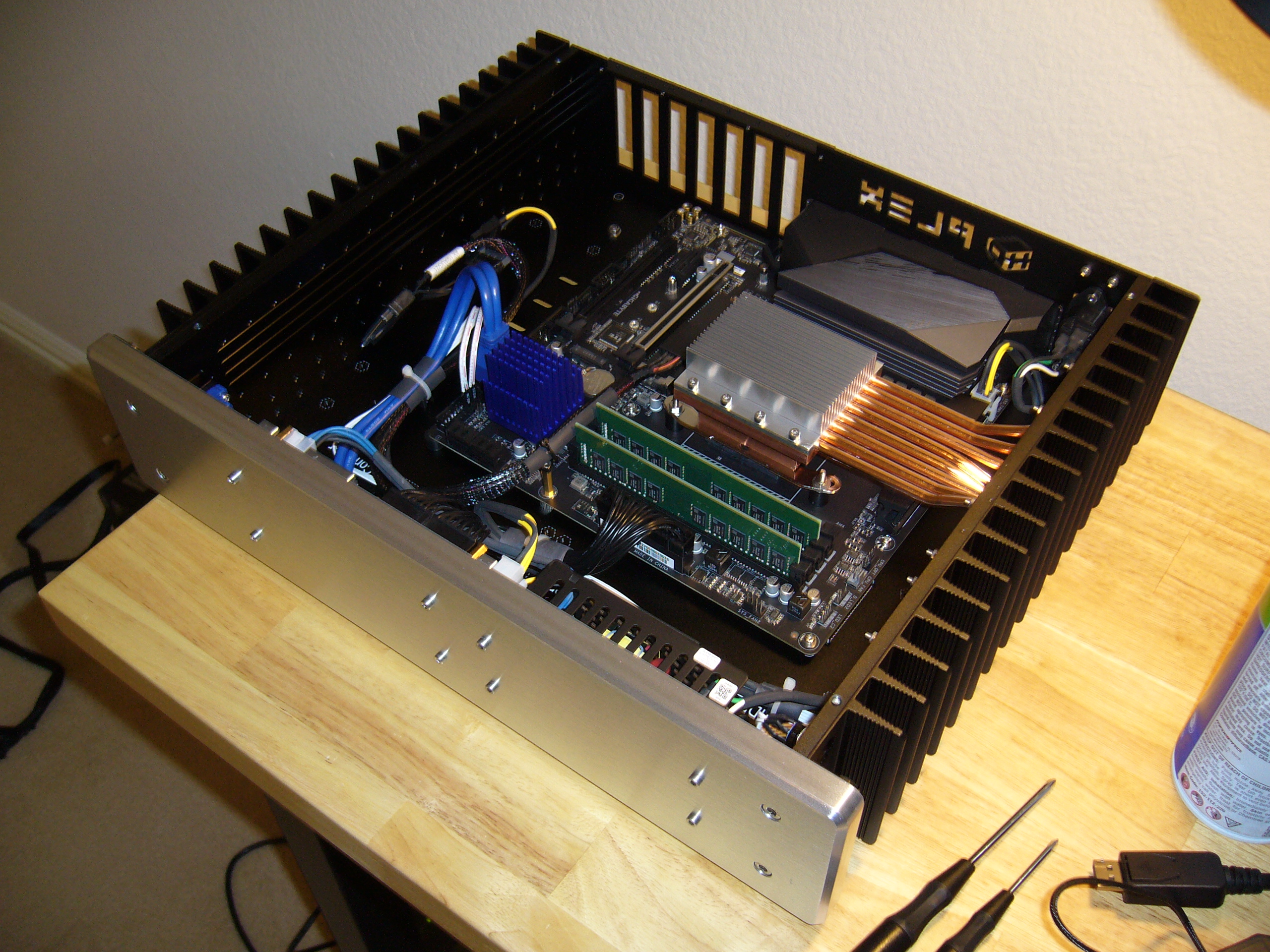
The low position of the SSD is deliberate. I actually cut a second mounting plate in case I wanted to install a second 2.5" SSD, which would install on the heat sink to the right (in the photo) of the first, toward the rear of the enclosure, and higher. The offset would allow me to plug in both U.2/U.3 cables within these rather tight confines. Note that the mounting plate for the cable tie mount has space for a second one above the first as well.
Note that in the photo the U.2 connector appears to be a bit askew. I will have to check (again), but I believe this is an illusion.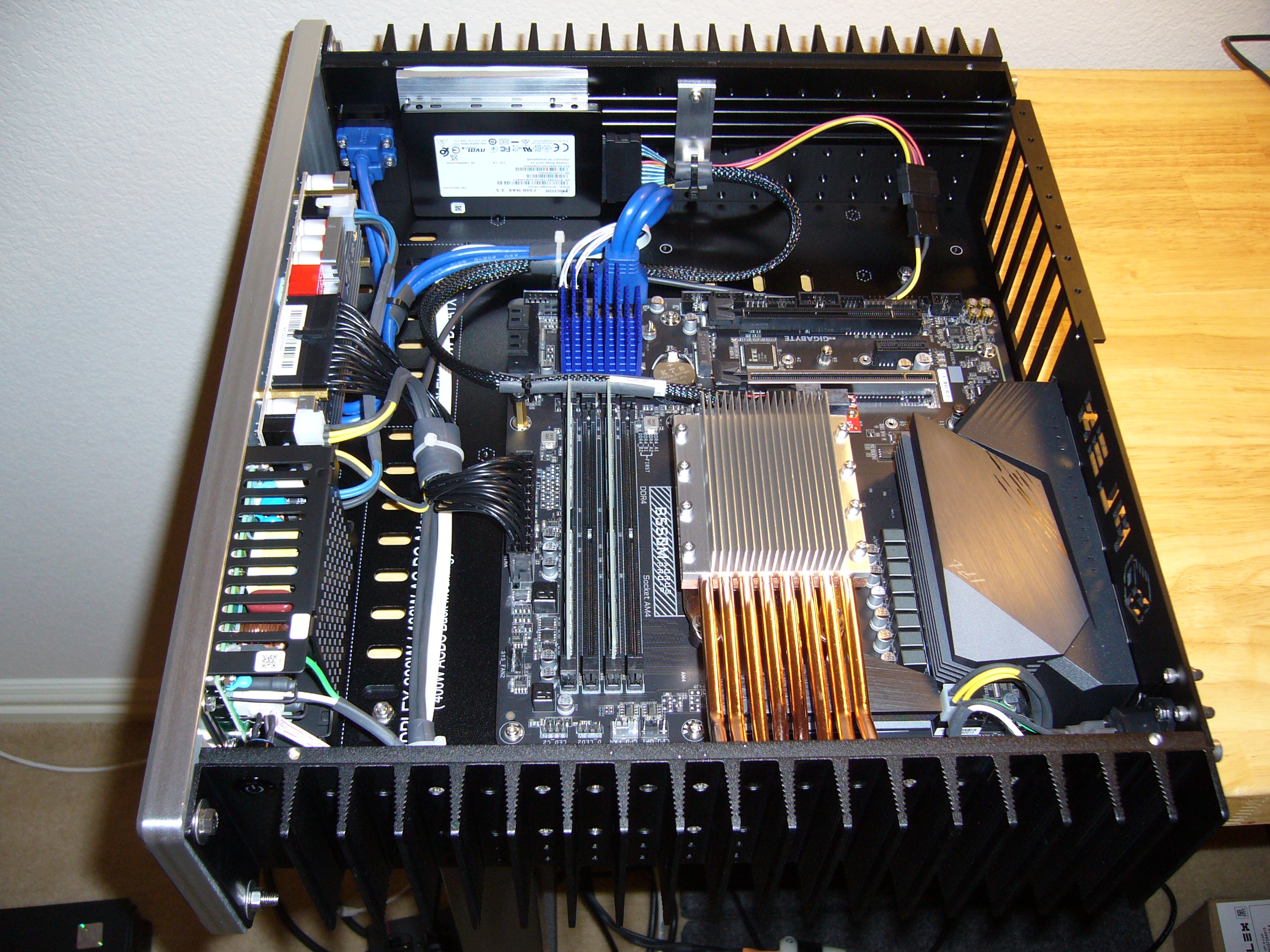 All done. What I did not show was the nightmare I had getting the SSD to work. To make a long story short, the BIOS on this motherboard requires the
CSM (Compatibility Support Module) to be enabled in order to recognize NVMe devices. Bizarre.
All done. What I did not show was the nightmare I had getting the SSD to work. To make a long story short, the BIOS on this motherboard requires the
CSM (Compatibility Support Module) to be enabled in order to recognize NVMe devices. Bizarre.
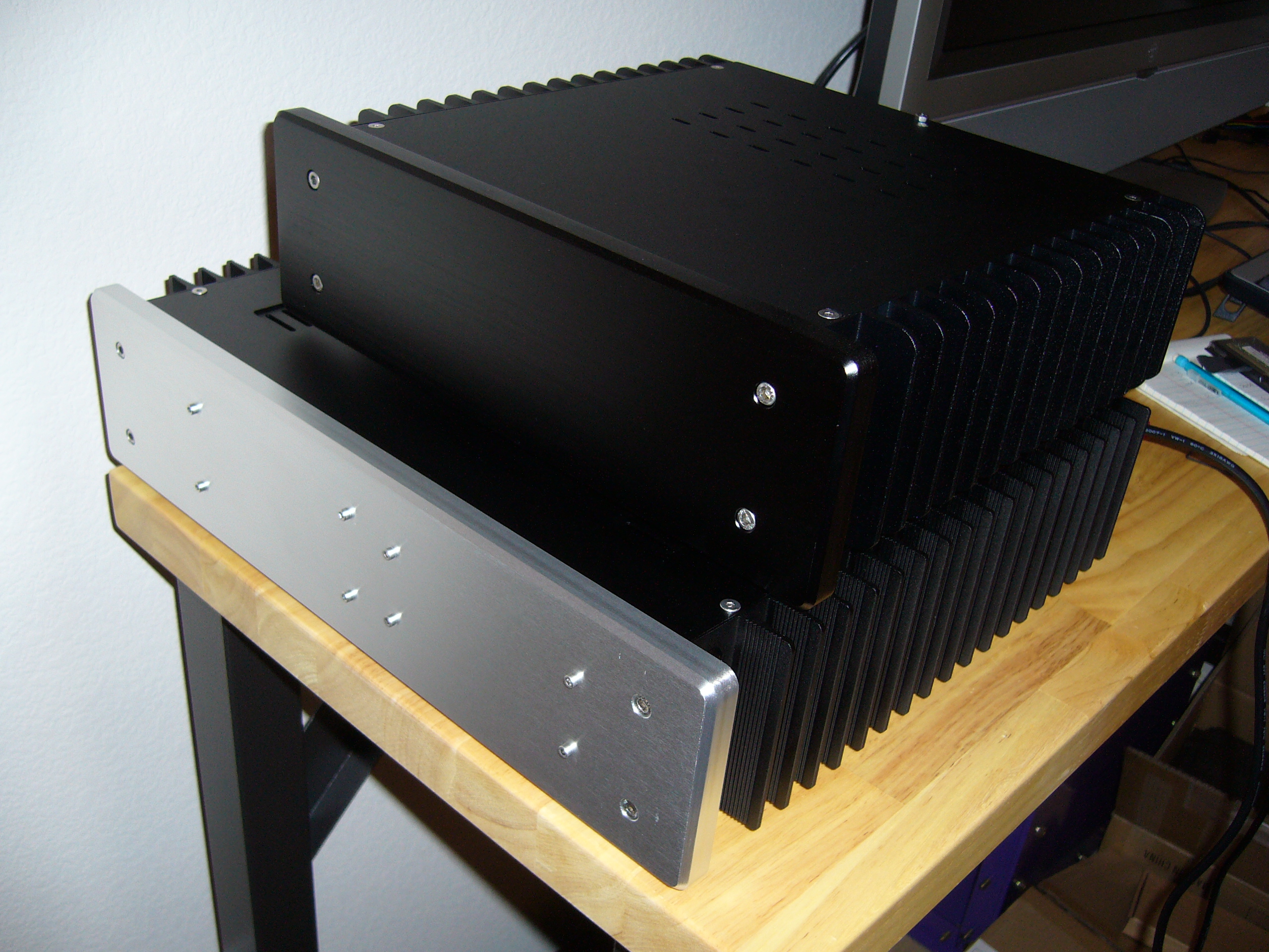 And here it is, with the H3v3 sitting on it.